


New Features in Sunbeam-B,T.H.
Page 36
Page 37
If you've noticed an error in this article please click here to report it so we can fix it.
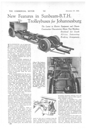
Trolleybuses for Johannesburg JOHANNESBURG, one of many progressive overs,--qs municipalities that are introducing trolleybuses for their city passenger services, recently placed an ordex with Sunbeam Commercial Vehicles, Ltd., liffoorfield Works, Wolverhampton, for 11 four-wheeled chassis of this type. The general layout of , their mechanical specification is similar to the machines supplied last year to Durban Corporation.
The electrical-traction equipment is designed for regenerative and rheostatic braking and includes an emergency runback preventer, whilst the main brake system is of the Sunbeam-Lockheed hydraulic type assisted by a vacuum servo motor. In this particular chassis twin vacuum tanks are employed, as both the brakes and the doors of each vehicle are operated from the same vacuum system.
With accommodation for 60 passengers, the double-deck bodywork, constructed by the Metropolitan-Cammell Carriage and Wagon Co., Ltd., is wider than the vehicles usually seen in this country, for in Johannesburg regulations permit of bodywork up to 8 ft. in width. The four-wheeled chassis has wheelbase and track dimensions of 16 ft. 3 ins. and 6 ft. 51 ins. (front) and 5 ft. 1 li ins, rear, the overall length and width working out at 26 ft. i in. and 7 ft. 9i ins. respectively. Complete with collector gear the chassis scales approximately 4 tons.
The main frame is constructed of high-tensile-steel channel pressings for the side members, braced with largediameter tubular members; in addition there is a diagonal pressed steel member amidships. As will be seen from accom panying illustrations, the longitudinals are upswept over both front and rear axles and afford a frame level of 2 ft. 1 in, between the arches.
Mounted in a subframe, which is attached to the main frame at four points through the medium of Silent bloc bushes, the motor, manufactured by the British Thomson-Houston Co., Ltd., gives 80 b.h.p. at 500 volts D.C.
It is of the compound-wound type de signed with a capacity for heavy overloads, the armature being balanced both statically and dynamically to ensure smooth running at the maximum speed of 2,646 r.p.m., the vehicle road n30 speed at this rate of rotation being 30 m.p.h. Regeneration of current is possible from all speeds above 11 m.p.h., and apparatus is supplied to provide automatic rheostatic braking when the speed falls below that at which regenerative braking is effective.
The motor is controlled by a foot accelerator of the plate type, operating a master controller switch which brings into use contactors carrying the main current; thus the controller switch carries only a light load to operate the solenoids on the contactor panels. The last-named are carried in the driver's compartment, in an accessible position, and are enclosed in polished-wood cabinets with readily detachable covers lined with asbestos.
A relay is provided in the shunt contactor panel, which comes into operation if the regenerative voltage exceeds that of the line, and inserts a resistance into the lighting generator circuit, thereby preventing any possibility of burning out the generator motor. Placed on the left of the driver, for hand operation, the reverser contains the necessary contacts for its essential function, whilst auxiliary contactors are so arranged that any mOvement of the handle from either running position immediately breaks the contactor clantrot circuit, causing all contactors to open before the main contacts of the reverser, There is an audible indicator to warn the driver of trolley dewirement. For this purpose, a switch is normally held open by the, 500-volt supply, but if a trolley leaves the overhead lines the switch closes and completes a buzzer circuit which is worked off the 24-volt auxiliary lighting service. The runback control is operated by a springclosed contactor coupled to a coil which is always energised when •the circuit breakers are closed. In the event of the power supply failing,. this contactor would close and short circuit the armature and series field windings, thus preventing the bus from running backwards down a hill at a speed greater than about 2 m.p.h.
There is also in the driver's cab an interesting indicator to record the amount of deviation of the trolley poles to left or right, from a central position parallel with the vehicle. Figures on either side of a zero mark are illuminated according to the extent of the deviation.
With the motor mounted amidships the transmission is compact and consists merely of one short tubular shaft from the motor to the rear axle. It incorporates Hardy-Spicer needle-roller universal joints. Of the underslungworm type, the rear axle embodies a steel drop-forged casing, the ends of which are ground to receive the spring brackets. The final drive consists of a hardened and ground steel worm meshing with a phosphor-bronze wheel, the reduction ratio afforded being 10.33 to 1.
All brake drums are 17 ins, in diameter, those mounted on the front axle having shoes 3 ins, wide, and those at the rear having 6-in. shoes. As indicated earlier, the foot brakes are operated hydraulically by means of the Sunbeam-Lockheed system, which comprises a master-cylinder box with two cylinders, one for the brakes of each axle, the outer casing acting as a fluid reservoir. A Clayton-Dewandre vacuumservo motor is interposed between the pedal and the master cylinders in such a manner that in the event of the vacuum system failing, the hydraulic brake can still be applied, through a direct linkage from the pedal to the pistons of the master cylinders.
Orte of the accompanying drawings shows the braking system in diagrammatic form and it will be noticed that there are two vacuum storage cylinders (one being smaller than the other) with
diverter valve interposed between them. The reason for this is to ensure an adequate depression for braking assistance, to be obtained as quickly as possible. To this end, the small vacuum cylinder is first exhausted by the rotary sliding-vane exhauster, the
diverter valve coming into operation when about 12 ins. of negative pressure have been generated. As we have already indicated, the dual vacuum containers are provided in order that the exit doors can be operated from the system.
It is interesting to note that a switch is installed in the control circuits, so that when the exit door is opened the current to the motor is cut off.
Interior lighting is effected by a lowvoltage generator and battery, The wiring incorporates a patented circuit whereby the battery is used only to supply the small amount of current necessary to operate the legal lights and such accessories as the screen wiper, horn, bells, etc., the main current load being taken from the generator unit and not from the battery. Good interior illumination is therefore provided without its being necessary to install a large battery. The system also obviates any necessity to run the motor generator except when the main interior lamp load is being taken.
The generator set consists of two insulated machines with a continuous capacity of 1,000 watts, the dynamo output being rated at 24 volts. It is interesting to note that the high voltage portion of the unit is entirely insulated from the main frame of the body and provision is also made to insulate the unit from the point of view of noise and vibration.
TO DOCP3