


A NEW FORM OF TIPPING GEAR.
Page 58
If you've noticed an error in this article please click here to report it so we can fix it.
A 116suine of Recently Published Patent Specifications.
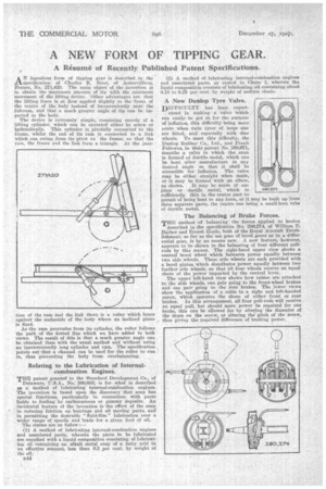
AN ingenious form of tipping gear is described in the specification of Charles R. Sirot, of Aubervilliers, France, No. 271,420. The main object of the invention is to obtain the maximum amount of tip with the minimum movement of the lifting device. Other advantages are that the lifting force is at first applied slightly to the 'front of the 'centre of the body instead of inconveniently near the fulcrum, and that a much greater angle of tip can be imparted to the body.
The device is extremely simple, consisting merely of a lifting cylinder, which can be operated either by screw or hydraulically. This cylinder is pivotally connected to the frame, whilst the end of its ram is connected to a link which can swing from its pivot on the frame, so that the ram, the frame and the link form a triangle. At the junc
tion of the ram and the link there is a roller which bears against the underside of the -body where an inclined plane is fixed.
As the ram protrudes from its cylinder, the roller follows the path of the dotted line which we have added to both views. The result of this is that a much greater angle can be obtained than with the usual method and without using an inconveniently long cylinder and ram. The specification points out that a channel can be used for the roller to run in, thus preventing the body from overbalancing.
Relating to the Lubrication of Internalcombustion Engines.
THE patent granted to the Standard Development Co., of Delaware, U.S.A., No. 260,602, is for what is described as a method of lubricating internal-combustion• engines. The invention is based upon the discovery that soap has special functions' particularly. in connection with parts liable to fouling by carbonaceous or gummy deposits. An incidental feature of the invention is the effect of the soap ` in reducing friction on bearings and all moving parts, and in permitting the desirable "fluid-film" lubrication over a wider range of speeds and loads for a given feed of oil. The claims are as follow :— (1) A method of lubricating internal-combustion engines and associated parts, wherein the parts to be lubricated are supplied with a liquid composition consisting of lubricating oil containing an alkali metal sOap of a fatty .acid in an effective amount, less than 0.5 per cent, by weight of the oil.
B44
(2) A method of lubricating internal-combustion engines and associated parts, as statedin Claim 1, wherein the liquid composition consists of lubricating oil containing about 0.15 to 025 per cent, by weight of sodium oleate.
A New Dunlop Tyre Valve. DIFFICULTY has been experi
enced in making a valve which can easily be got at for the purpose of inflation, this difficulty being more acute when twin tyres of large size are fitted, and especially with 'disc wheels. To meet this difficulty, the Dunlop Rubber Co., Ltd., and Frank Fellowes, in their patent No 280,671, describe a valve in which the stern is formed of ductile metal, which can be bent after manufacture to any desired angle so that it shall be accessible for inflation. The valve may be either straight when made, or it may be formed with an elbow, as shown. It may be made of one Piece or ductile metal, which is sufficiently thin in the centre part to permit of being bent to any form, or it may be built up from three separate parts, the centre one being a small-bore tube of ductile metal.
The Balancing of Brake Forces.
THE method of balancing the forces applied to brakes described in the specification No. 280,274, of William E. Barber and Ernest Hoyle, both of the Royal Aircraft Establishment, so far as the use goes of bevel gears as in a differential gear, is by no means n&*. A new feature, however, appears to be shown in the balancing of four different pullrods by this means. The right-hand upper view shows a central bevel wheel which balances power equally between two side wheels. These side wheels are each provided with a bevel pinion which distributes power equally between two further side wheels, so that all four wheels receive an equal share of the power imparted by the central lever.
The upper left-hand view shows bow cables are attached to the side wheels, one pair going to the front-wheel brakes and one pair going to the rear brakes. The lower views show the application of a cable to a right and left-handed screw, which operates the shoes of either front or Tear brakes. In this arrangement, all four pull-rods will receive an equal pull, but should more power be required for one brake, this can be allowed for by altering the diameter of the drum on the screw, or altering the pitch of the screw, thus giving the required difference of braking power. •