


HINTS ON MAINTENANCE.
Page 56
If you've noticed an error in this article please click here to report it so we can fix it.
How the Frame of the 4-ton A.E.C. can be Extended. Obviating Awkward Breakages in Cylinder-head Bolts. Notes on the Morris Switchboard.
Extending the Frame of the 4-ton A.E.C.
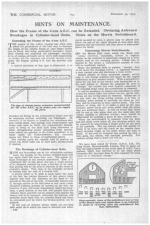
THE maker of the A.E.C. chassis has often been asked for particulars of the best way to increase the length of the chassis frame so that longer bodies can be fitted, this being particularly necessary where such chassis are employed for passenger carrying. It is, of course, advisable not to carry such lengthening to excess, hut the company can provide various extensions, the longest adding 3 ft. and the shortest only 7 ins.
A typical extension of this type is illustrated ; it is intended for fitting fo the pressed-steel frame and can be employed without extending the tivheelbase. If, however, it be desired to lengthen the wheelbase also, new cardan shaft, rear springs, rear cross-member and brake rods must be fitted, the cross-member immediately in front of the back axle being shortened to allow strengthening plates (extending from immediately behind the gearbox to the frame extension) to be fitted inside the frame-members. The extension pieces are fitted to these strengthening plates.
The various parts are usually held in position by rivets, but fitted bolts can be used quite satisfactorily if desired.
, The Breakage of Cylinder-head Bolts WITH the increasing use of the detachable cylinder head, the trouble of the broken cylinder-head bolt has made itself felt more than ever. The reason for these breakages is not always understood. Now, if A cylindrical bar of any given size has a small portion of its diameter reduced by even a fraction of an inch, that portion will be the first to fracture in the event of excessive strain. This, then, is the principle involved in dealing with the risk of a broken bolt.
. A groove about sig in. wide is made under the head of the bolt, the bottom diameter of this groove being slightly less than the diameter at the base of the threads at the end of the bolt. It naturally follows that if, through carbon in the bolt holes or any other cause, excessive twisting stresses be exerted on the bolt, the fracture, if any, will occur Immediately under the head ; thus, a good portion of the bolt will project from the cylinder block, and this can be gripped and enables the broken bolt to be removed; otherwise the fracture will probably occur flush With the cylinder block and leave no convenient part by which the-broken portion can he gripped.
In the case of cylinder blocks which are provided with studs on to which the head is lowered and afterB42
wards secured by nuts, a groove may be placed just below the end of the upper threads on each stud, thus ensuring that the fracture will take place at some point above the block.
Concerning Morris Switchboards.
ON the Morris light vans, which are fitted with Lucas electrical equipment, failure to register charge on the ammeter is sometimes caused by a worn contact stud on the charging switch. Unless this be located at the outset, a considerable amount of time will be needlessly wasted.
When the ammeter fails to register "charge," first of all move the charging switch. A tightness denotes a bent contact arm and slackness a loose screw.
Should neither of these symptoms appear, switch corr to the charge position and speed up the engine sufficiently to give normal output. With a screwdriver press the top end of the contact arm backwards on to the stud behind it. Should the ammeter fly over to "charge," the trouble has been located—especially if ,the charging stops when the screwdriver is removed. It will be necessary to remove the switchbox in order to put the switch right, and before the box can be withdrawn all the wiring must be removed. Unless one is au fait with the Lucas wiring system, it is best to introduce some system of marking the wires so that they will be replaced in their correct order. The best method of doing this is to make a plan of the nine terminal screw boxes and write under each the wires that are anchored there. It will be found that there will be one or two wires that are the same size and colour, leading to different screws ; these should be differential by twisting a piece of wire around one.
• When the switchboard is removed from the dash and the metal cover taken off, the charging switch can be removed by unscrewing a single screw at the back of the assembly. The top contact stud will usually be found to be worn and the track on the ebonite baseboard showing rough at the point where the stud is fitted. If the stud be removed and packed up with a thin shim, the switch will function perfectly. The cushion spring from a Ford coil will do.
We have been asked by Tylors (J.B.4), Ltd., 134, King Street, Hammersmith, London, W.6, to point out that the improvement to the valve caps of A.E.C.-Tylor engines, which was referred to in our issue dated December 6th, has been done by this company for some sears at a standard charge.