


FEATURES OF AND IMPF :MENTS IN 1928 DESIGN.
Page 46
Page 47
Page 48
Page 49
Page 50
If you've noticed an error in this article please click here to report it so we can fix it.
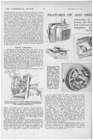
Lubricating the Brakes and Sell with Universal Jc Suspension. Eni
3. Pointers on ices. Progress The Problerri of :ooling. Bogies
for Si
Tprogress recently made in the design of chassis 1 has been so great as to confound the critics of our commercial vehicle industry and to prove to them in no uncertain manner that it is fully alive to future possibilities and straining every nerve to win and retain a preeminent position in the world's markets for transport vehicles. At home the premier position has indubitably been obtained, and abroad there are signs that British-built vehicles and appliances are winning through, but progress must not be based only upon vehicles as a whole; scrupulous attention must always be paid to detail, in the same way that cheap bricks should not be used to build up a beautiful edifice, and much can be said against, or in favour of, certain tendencies and practices in the construction of chassis.
In this article we have picked out various points in chassis construction, criticising or giving praise where it be due, and we have endeavoured to show the benefits afforded by adopting certain methods. We have not confined ourselves to details of British-built chassis, its it is obvious that much can be learnt from a study of the features of foreign products, whether marketed in this country or not.
Chassis Lubrication.
. Considerably more attention has been given of late to the adequate lubrication of various parts of the chassis and to the retention of the lubricant, and we are glad to see more use being made of oil in preference to grease. The latter has never appealed to us greatly as a satisfactory material, as it often contains moisture, easily clogs if left unattended for a short time, and /nixes with dirt to form a stiff paste which sometimes becomes immovable by the grease gun. Apparently its only real advantage in the past lay in the fact that it is easier to retain it in a bearing and more precautions have to be taken where oil is employed, otherwise the oil is easily lost.
Grease does not lend itself well to continuous lubri cation. Its action is what may be termed spasmodic, and it is usual to give a surplus of grease once in a while and hope for the best. With oil, reservoirs affording a continuous supply can be provided for such parts as the shackles, as is arranged on the Pagefield and Reo, or ordinary ripples for high-pressure oiling can be utilized, and there is but little risk of these or their connections dogging.
Suitable oil can be trusted to find its way by gravity from some raised reservoir. This is done in Ripanit's Alcyl system of centraliAN1 lubrication, whereas in the Karrier six-wheeler the supply of oil is ensured by spring plungers which exert continuous pressure, and, in this case, the supply is graded according to the needs of the bearing by nipples of various sizes.
1132
In the Alcyl method the how by gravity is assisted by the capillary action of wicks contained in metal flexible tubes-leading to the various points at which the lubricant is necessary, and at these poiats there are adjustable bolts, which are regulated in the first instance to release the amount of oil necessary for each particular bearing. The oil employed is the same as that used for the engine, and the oil reservoir has a capacity for about half a pint, which is said to be sufficient for approximately 1,000 miles of running with a light vehicle, and the only attention necessary is the replenishment of this reservoir, which is a matter of a minute's work every week or two. It is claimed that no oil escapes anywhere in the system; there is no dripping and no overflowing, and as the oil reaches the lubricating points from the inside, mud and dust cannot penetrate into the lubricating holes, as is possiblewhen the 011 I s inserted from the outside.
Oil and grease retainers are many and varied. The ordinary return thread, whilst satisfactory enough where the lubricant is not under pressure, can hardly be considered as highly efficient where pressure is employed, even if this be low.
Some of the simplest devices have proved of value. For instance, in the Garner universal joint the oilretaining gland consists of a felt washer carried within clock spring costing approximately 3d., the advantage of this form of retainer being that the washer can float with a shaft which is running out of centre, as Is usually the case with a propeller shaft one end of which is moving up and down with the axle.
Two other simple types are employed on some of the Scammell products. One of these is a felt ring, carried in a channel formed in the two parts, between which there is relative motion, and secured in this channel by means of a hose clip. This enables any degree of pressure to be applied and permits adjustment as required. The second device consists of a ring of chrome leather carried close to its periphery by one part and pressed at its centre against the other part by means of small spiral springs. This method has proved most efficient.
Spring-loaded cup seals are utilized • in certain parts of the new Leyland chassis. For instance, each of the axle shafts has three of these.
In the lubrication of hub bearings it is of vital importance that oil and grease do not enter the brake drums, as they materially reduce the coefficient of friction and constitute a danger. If it be found impossible to prevent leakage from axles or hub bearings— and even the best of retainers is apt to give trouble after a long life—then it is sound policy to provide some outlet for the oil or grease Which will carry it clear of the drum or drums; baffles may have to be utilized. This is a point which does not always receive the attention which it justifies. In addition, tyres, both solid and pneumatic, quickly deteriorate if kept for long in contact with the usual forms of lubricant.
Occasionally, leakage of lubricant may be traced to some simple cause, such as failure to provide a pressure-release device.. This is an essential fitment for .
such parts as the rear axle and gearbox, for immediately these warm up in service the air and lubricant contained in them are expanded and the lost-named may be practically forced out. In the Fiat T-shaped axle casing such a device Will be found at the forward end of that part of the axle forming thetorque member.
Trouble Is frequently experienced through en inadequate supply of lubricant to the clutch-spigot bearing, And in certain modern designs particular attention has been paid to this point, as, for instance, in the t-Ww Leyland and Coalmen In the Leyland provision is madefor lubricating this bearing by oil gun, whilst In the Commer it forms part of the general system of engine lubrication, but the oil only flews to the spigot when the clutch pedal is depressed, and, of course, this is the only time that there is relative movement between the halves. of the bearing.
Brakes and Servo Devices.
In several chassis both of British and foreign makes there has been a return to the employment of transmission brakes positioned immediately in front of the rear, axle, and with the shoes anchored to the axle casing. Such a position naturally increases the unsprung weight and increases the liability to noise caused by rattle of the shoes, etc., but it presents the advantage that the braking stresses do not have to be transmitted through the cardan joints; so, probably, the pros and cons are fairly evenly balanced. Another consideration in this connection is that the length of the operating rod or cable must be considerably greater.
What may be termed a mean between the brake inmediatelY behind the gearbox and that situated in front of the rear axle is the type of brake which forms a unit mounted on cross-members at some point between these two positions. This relieves the first portion of the propeller shaft, and the braking torque is carried through the joints of the rear portion only. The position appears to be a good one, as the brake can be adequately cooled and can usually be made readily accessible through a trap door in the floor of
the body. A good example of this construction is to be found on the Halley.
As a result of the call for more powerful braking in the ease of high-speed and heavy commercial vehicles and the 'employment of brakes on more wheels than two, a need has "shown itself for devices which assist the driver's manual effort in operating the brakes.
The most popular type of servo employed at present is the Dewandre, operated by vacuum, whilst on certain chassis use is made of. the Westinghouse device, in one form also utilizing the engine suction as its source of power, whilst air under pressure is used in another.
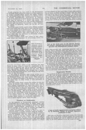
Some fears have been entertained regarding the possibility of such devices failing at critical moments through the fradtaring of a connecting pipe, and, in our opinion, every effort should be made to safeg,uard the . vehicle by linking up the operating gear in such a manner that the driver can still operate the brake efficiently by his own effert, although, naturally, he would have to use much greater pressure on the pedal. We noted particularly that such a dual control is provided on the Karrier DD6/1 six-wheeler, although, in this instance, the braking IS effected on the Westinghouse air-pressure system.
ill
If there be any question of difficulty in combining servo and manual operation by one pedal, there is apparently no reason why a second brake pedal should not be employed, for it is interesting to note, in at least one commercial vehicle, the Cottin and .Desgouttes, that there are two brake pedals, apart from the handbrake lever, although, in this case, the extra brake is supplementary and not specially provided for use in conjunction with a servo device.
A particularly interesting form of brake-compensating gear is employed on the Morris. This consists of a sprocket carried in a -.fork secured to one of the brake-operating rods. The ends of the small length of roller chain which passes around this sprocket, are connected to links attached to the operating rod of the other brake and to the lever of the cross-shaft respectively. As will readily be seen from out illustration, this provides a very simple and effective form of balance gear.
Two other of our illustrations show the arrangement of the . front-wheel brakes on the latest Associated Daimler passenger chassis, in which light alloys are utilized to a far greater extent than is normally the case. It will be seen that both the shoes and the shoe carriers are in light metal. The shoes are well-ribbed • and present the advantage that the extra surface afforded by the ribbing, combined with the excellent B34 heat-condactivity of the metal, should make these brakes very cool in operation.
The braking on Dennis passenger vehicles is particularly good, and every care is taken to prevent the ingress of dirt-and water. As will be seen from a, sketch, the arrangement of the dual drums is quite simple, and the operating rods pass through the dust covers. ,
Certain makers have found that pressed-steel brake drums are not only apt to distort under pressure and heat unless made of very thick material, but the surface tears and then becomes so rough that rapid wear of the shoe facings ensues. Consequently, more use is now being made of cast-iron liners. A particular example of this construction is to be found in certain of the new Star chassis, in which the main drums are cast in one with the wheels.
Liners can be made easily and cheaply renewable, but -care should be taken to ensure that they are strongly secured, so that there is no danger of movement occurring between the liners and their carriers. .
On some chasSis forceful application of the brakes causes bending of the cross-shafts, particularly if the levers be some distance from the end bearings of the shaft, and this, whilst not being dangerous, means loss of pedal movement.On the new Pageileld chassis the bending is obviated by providing a central stay stretching from the middle of the diagonal frame bracing and clipped round the cross-shaft.
Steady progress has been made, in the development of universal joints which will stand up to the exigencies of modern propeller-shaft speeds and engine 'torques. The old flexible fabric joint without any centring device is proving unsatisfactory, particularly in positions where it is subjected to much flexing and where a long shaft may be rotating at a fairly high speed. The slightest Bing of the shaft not only throws considerable stresses upon the joints, but becomes a very disagreeable source of vibration, which can be felt all over the vehicle.
To obviate such trouble, nearly every chassis equipped with these joints has some form of ball centring device, and these appear to be satisfactory. In other chassis metal universal joints have replaced the fabric type, but the great problem with these joints is so to construct them that the lubricant is effectively retained over -long periods of usage.
Another problem which has arisen is that where these joints are contained in oil-retaining covers the
powerful centrifugal action on the lubricant has been found, in many .cases, to cause the constituents of the lubricant to separate out, and to avoid this trouble at, least one maker, Hardy, Spicer and Co., Ltd., -Birch Road, Witton, Birmingham, has brought out a special form of non-separating grease, particularly for use with joints of this description.
A neva form of all-metal joint which strikes us as being particularly efficient is that designed and built by the Kirkstall Forge, Ltd., near Leeds. This joint permits an angular movement of 30 degrees to each side of the centre line; in other words, a total movement of 60 degrees.
The ring casing which carries the bushes for the two spiders is formed with hollows between the bushes, these hollows constituting oil reservoirs, which are in communication with each other and are tilled by removing a single plug of adequate dimensions. One side of the ring has a sealing plate which is never disturbed after the first fitting. The oil is fed to the various surfaces by the centrifugal action set up in the joint, this action being assisted by small deflectors at the sides of the bushes, which are of the blind type, and thus leakage when running is practically 'impassible. The joint is proof against water, mud and dust.
Pointers on Suspension.
In the majority of British-built passenger vehicles considerable use is being made of rubber under compression as a means for providing an increase of spring strength approximately proportional to the load. Rubber springs, as they may be termed, are simple to fit, moderately cheap and have a long life.
Springs automatically variable to load are used to a limited extent, a specific example being the Bristol.
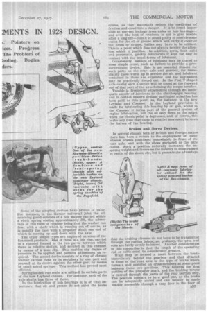
In International vehicles a quarter-elliptic auxiliary spring is mounted over the main, leaf of each rear spring, whilst in the bus chassis built by the Relay Motors Corporation, of Limn, Ohio, two quarter-elliptic laminated springs are employed above each main spring of the rear axle; these are mounted together in a frame bracket situated at the inner side of each side, member. One of these auxiliary springs is longer than the other, and this is the first to come into action. It makes contact with a flat-faced bracket forming part of the axle casing, whilst the second auxiliary spring contacts with one of the plates of the first auxiliary. Each of these springs has a block at its outer end, this block carrying some long-wearing and cushioning material, such as Ferodo, which prevents noise and takes up any wear. The design of this form of suspension is such that, with the body on the chassis, the first auxiliary spring comes into action, whilst the second spring makes contact with the first when 75 per cent. of the seats are full.
The taping of the springs shown in our illustration was carried out on the first few sets only to prevent noise caused by the spring plates making contact with each other, but in later designs the breaking of contact was prevented by putting a slight set in each leaf.,
In examining one vehicle of a certain make, we found to our surprise that bolts in shear were employed for securing the front springs. We should have thought that the experience of the makers would have prevented such an obviously technical error.
Suspension Details.
The problem of efficient suspension does not rest solely upon the type of spring employed. Much can be done by attention to details, such as spring shackles, and there are signs that increasing efforts are being made to improve upon the ordinary form of shackle-pin and bush. For instance, in the new Lancia Omicron chassis the shackles are provided with Timken taper roller bearings, whilst in the new Sanrer use is made of compressed-rubber buslips.
Side play on shackles sometimes causes objectionable noise, and in the latest Leyland models the shackle-pin bushes are flanged and can be adjusted to take up any play in the first instance or as the result of wear.
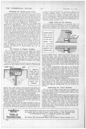
Mounting the Change-speed Lever.
In previous articles we have referred to the increasing tendency towards the adoption of single-rod control of the selector mechanism, but we have said little about the actual change-speed lever itself and the manner in which it is mounted; for instance, in the latest Commer chassis the lever is mounted on the floating principle, which we believe was originated by Rolls-Royce.
This form of lever is illustrated. It is simple and, apparently, most effective. Near the lower end of the lever is an enlargement faced at each side to work between the arms of a forked lever on the change-speed cross-shaft, a pin passing through the fork and a hole in the brake lever. The lower end of the last-named works in a runway formed partly by the lower portion of the change-speed-gate bracket and partly by a plate which is bolted to this bracket, This permits the lever to work backwards and forwards and to carry with it the forked lever on the crass-shaft, but immediately the side pressure Is imposed the hand lever fulcrums on its lower end and forces the tross-shaft to slide in or out to correspond with the various sections of the gate.
In nearly every case the old box form of gate has been dispensed with, as this form of structure lends • itself to jamming caused by the presence of dirt or through the insertion of small stones, etc., by the mischievous.
The Control of Engine Cooling.
The average cooling system of the engine of a motor vehicle is designed to prove effective when the vehicle is working under the worst possible conditions; consequently, for most of its time the cooling is excessive. This applies particularly when the temperature of the atmosphere Itself is low, and, as a result, one sees hundreds of radiators disfigured by pieces of cardboard, paper, etc., added, in an effort to reduce the cooling area exposed to the air.
In it few cases proper provision has been made for the addition of more tightly radiator blinds or blocking-off panels, but a still greater improvement now being utilized on a number of vehicles is radiator shutters, which can be set exactly to suit the circumstances, as, for instance, completely shut when starting up from cold and wide open when hill-climbing in hot weather.
Efforts have been made to operate such shutters automatically by the aid of a thermostat control, but this is hardly sufficiently advanced to form a commercial proposition, and it is for the present quite sufficient to provide an easily operated hand control, such as that used on the Bristol radiator.
The trouble with some of these shutters is that as each vane of the shutter is movable and must be carried in bearings, rattle is apt to occur, and to avoid this in the case of the Bristol radiator the shutter vanes are mounted in fibre strips and the operation is effected by a handle working along a sector on which are cut ratchet teeth. The handle communicates with the shutters through the medium of a cable and the shutters have a return spring. This radiator, complete with the shutters, is built by Spiral Tubes and Components Co., Pembroke Street, London, N.1.
Bogie Units for Six-wheelers.
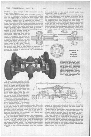
An interesting development in connection with the construction of rigid six-wheelers lies in the provision of bogie axles complete with brake gear and suspension springs‘ and .prOvided with brackets all ready to bolt
to the chassis frame. These are being built by the Kirkstall Forge, Ltd., near Leeds, and embody the patent Kirkstall axles, each of which is made from a single drop forging of high-grade alloy steel. The steel billets employed are rolled from ingots, and during the rolling the fibre structure of the steel is developed in the direction of the length of the billet, and during the drop forging this structure follows the direction of the flow of metal.
It is rather interesting to find that in the Kirkstall bogie an extra differential is embodied in the foremost axle, thus balancing the drive to the two axles.
The anchorage of the inverted semi-elliptic springs is particularly effective and rigid. Use is made of the Woodhead divided main-leaf type of spring, so that it is impossible for any fore or aft movement of the spring in its anchorage to occur ; lateral movement is prevented by the casting forming the spring beds.
Each axle has a dipstick, combined with which is an air vent, and each bogie incorporates Kirkstall universal joints of the new type, to which reference is made elsewhere. It should be noted that the universal joints and dipstick arrangement are all covered by patents.
Improving the Track Machine.
One of the criticisms which used to be levelled at the cross-country vehicle equipped with rubber track bands was that the drive was not positive and that slip would sometimes occur.
However, great improvements have been made in this direction, and the latest type of Kegresse-Hinstin band embodies a positive drive, which takes the form of two rows of studs on the inner side of each band, which engage with corresponding holes in the rim of the driving pulley. These steel studs or bolts, although rounded, are inclined to be noisy, and a still further improvement has been effected in the case of the CroS,sley-Kegresse, in which bands with fibre blocks are used in lieu of studs.