


AN ORIGINAL DES R• A SIX-WHEELER.
Page 14
Page 15
Page 16
If you've noticed an error in this article please click here to report it so we can fix it.
IF THIS WEEK, in pursuance of our promise to go further into the question of spreading thc load over more than the four axles that have hitherto been the conventional number, we refer to road-surface conservation, it is because road destruction, vehicle wear and tear, and tyre abrasion are all bound up together. The same influences are at work throughout, and if we can, by a change in vehicle design, reduce vibration and impact between the wheels and tht road, it seems absolutely reasonable that we should expect to produce :—
a lighter chassis of the same weight-carrying capacity, using cheaper and lighter components and to effect :— less road damage, a saving in running costs, a reduction in maintenance charges, an addition to passenger comfort, ..a diminution of risk to fragile loads, an approach towards greater safety by reason of better adhesion and improved braking and spragging possibilities and to justify :— higher permitted speeds on the road, even some relief from taxation.
It was with all these ends in view that we put forward, in our issue of December 13th, a suggested design of six-wheeler, in which the load is carried on four front wheels (two on each stub axle) and four driving wheels, the front pair of which should assist in the steering.
. For our present pur Pose we will take the design of chassis in whieh the wheels forward of the rearmost axle steer and a differ-. ential action between all the driving wheels. is permitted. It is, of. course, desirable that simplicityGof construction should be the keynote, as too great a measure of complicas time would only result in . failure, adding to weight and expense. This object has been kept in view in the design of the front-wheel arrangement included in the six-wheeler described and, illustrated a fortnight ago; whereby the weight is distributed over four whetIs without making t he
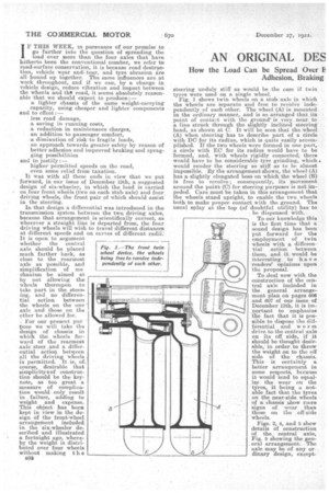
p3i steering unduly stiff as would be the case if twin tyres were used on a single wheel. Fig. 1 shows twin wheels on a stub axle in which the wheels are separate and free to revolve independently of each other. The wheel (A) is mounted in the ordinary manner, and is so arranged that its point of contest with the grounds is very near to a line struck through the slightly inclined steering head, as shown at C. It will be seen that the wheel (A) when steering has to describe part of a circle with DC for its radius, which is quite easily accomplished. If the two wheels were formed in one part, a circle with EC for its radius would have to be formed, and, with wheels rigidly connected; there would have to be considerable tyre grinding, which • would render the steering so stiff as to be almost impossible. By the arrangement shown, the wheel (A) has a slightly elongated boss on which the wheel 03) is free to revolve; consequently, its movement around the point (0) for steering purposes is not impeded. Care must be taken in this arrangement that the wheels stand upright, to enable the two wheels both to make proper contact with the ground. The usual splay at the top (of doubtful utility) has to be dispensed with.
To our knowledge this is the first time that a sound design has been put forward for the employment of twin wheels with a differential action between them, and it would be interesting to have readers' opinions upon the proposal.
To ,deal now with the construction of the central axle included in the general arrangement plan on pages 606 and 607 of our issue of December 13th, it is im. Portant to emphasize the fact that it is possible to dispose the differential and worm drive to the central axle on its off side, if it should be thought desirable, in order to throw the weight on to the off side of the chassis. This is certainly a better arrangement in some respects, because it would tend to equalize the wear on the tyres, it being a notable fact that the tyres on the near-side wheels of a chassis show more 'signs of wear than those on the off side wheels.
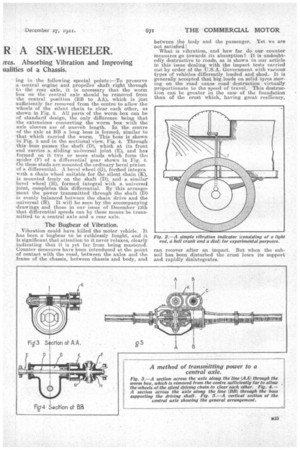
Figs. 3, 4, and 5 show details of construction of the central axle, Fig. 5 showing the general arrangement. The axle may be of any or dinary design, except
ing in the following special points :—To preserve a central engine and propeller shaft right through to the rear axle, it is necessary that the worm box on the central axle should be removed from the central position (BB to AA), which is just sufficiently far removed from the centre to allow the wheels of the silent chain to clear each other, as shown in Fig. 5. All parts of the worm box can be of standard design, the only difference being that the extensions connecting the worm box with the axle sleeves are of uneveh length. In the centre of the axle at BE a long boss is formed, similar to that which carried the worm. This bass is shown in Fig, 5 and in the sectional view, Fig. 4. Through this boss passes the shaft (D), which at its front end carries a sliding universal joint (E), and has formed on it two or more studs which form -Cho spider (F) of a differential gear shown in Fig. 4. On these studs are mounted the ordinary bevel pinion of a differential. A bevel wheel (G), formed integra with a chain wheel suitable for the silent chain (IQ, is mounted freely on the shaft (D), and a similar bevel wheel (H), formed integral with a universal joint, completes this differential. By this arrangement the power transmitted through the shaft (D) is evenly balanced between the chain drive and the universal (H). It will be seen by the accompanying drawings and those in our issue of December 13th that differential speeds can by these means be transmitted to a central axle and a rear axle.
The Bugbear of Vibration.
Vibration could have killed the motor vehicle. It has been a bugbear to be ruthlessly fought, and it is significant that attention to it never relaxes, clearly indicating that it is yet far from being mastered. Counter measures have been introduced at the point of contact with the road, between the axles and the frame of the chassis, between chassis and body, and between the body and the passenger. Yet we are not satisfied What is vibration, and how far do our counter measures go towards its absorption? It is undoubtedly destructive to roads, as is shown in our article in this issue dealing with the impact tests carried out by order of the U.S.A. Government with various types of vehicles differently loaded and shod. It is generally accepted that big loads on solid tyres moving on the road cause road destruction virtually proportionate to the speed of travel. This destruction can he greater in the case of the foundation than of the crust which, having great resiliency, can recover after an impact. But when the subsoil has been disturbed the crust loses its support and rapidly disintegrates.
Inn heavy vehicle like a motor coach, conditions are very different from those obtaining in an ordinary pleasure ear, Where solid tyres are used, two different kinds of vibrations are experienced. In travelling over a road with 'many pot-holes or a bumpy surface, vibrations which may be described as large waves are felt, and springs capable of long movement are needed to deal with them, as the deflections necessitate c siderable in o v ement. In travelling over a road of stone setts, sspeeially those in the North of England, where Fig. 6.— A suggestion for applying t he setts s r e to shackles the rocker principle used placed far apart, in chain construdion.
a vibration. i s experienced similar toswhat would be felt if the vehicle were running over a number of round bars placed elose together. This class of vibration causes a general rattle of all loose parts, and may be described as a tremor. Pneumatic tyres undoubtedly deal with this class of vibration better than any other means, but, in cases where. they cannot be used, it may he well to see what kind of spring is hest adapted to deal with this tremor class of vibration.
The long movement springs referred to above are of very little use in dealing with a tremor. Fully to appreciate the truth of this, it is only necessary to make the simple vibration indicator shown in Fig. 2, which consists of a light rod and bell crank. The rod should be attached to the axle, and the fulcrum of the crank to the body in a, place where its movements can be easily observed. With ordinary springs, when travelling over a stone. sett road, very little movement of the crank will be seen, although a very. objectionable vibration may be felt. This means that the springs are not able to respond to such quick movements, and that the whole vehicle is vibrating instead of the springs doing their work.. There is no doubt that the friction of the shackles and any other moving part, apart from the actual flexing of the spring, has a great deal to do with preventing the springs from responding properly.
Experiments with the indicator will show the difference between a properly lubricated and free shackle and one that is so stiff that it can hardly be moved. Greater attention should be bestowed on shackle joints, and thc... idea of their being "water lubricated " (which means not lubricated at all) is nonsense. To get the best results from springs, shackles should be frictionless. Experiments with roller bearing shackles have shown that they will allow springs to respond to vibration to a very mach greater extent than with ordinary joints.
i There s; however, a • difficiilty in the application of roller bearings to shackles, as the rollers impinge almost continually in one place, and in time ‘vear hollow s, into which they rest, and will no longer act.
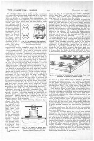
A suggestion is 3334 made in Fig. 6 of applying the rocker principle, which has been used in chain construction, to shackles. The rocker seems parti'eularly suited to i this part, as it is very free n action. The matter of lubrication of shackles is receiving more attention, and at the last Commercial Vehicle • Show oil caps were fitted to a great many vehicles instead Of grease cups. It may be said that grease can be forced, whilst oil can only gravitate, but the forcing of grease will only result in its finding the easiest way of escape, which is certainly not by forcing'', its way between the surfaces supporting the weight of the vehicle. Oil is better for this purpose, and its use should be encouraged. Lubrication between the leaves of the springs and the use of gaiters should be more general. Springs interposed between the chassis frame and the body shown in Fig. 7 have been tried with great success, provided their strength is properly proportioned. The mistake generally made is in having either too many springs or springs of too great a strength. A satisfactory spring can be made of wire, in. diameter, wound into a coil of 2 ins. diameter, 21 ins. high, properly hardened and tempered. The fixing is simple, as, if the lowest coil is larger than the body, a plate will hold it down to the chassis channel, and a central bolt will hold
the top to a plate which can be fixed to the body by means of coach screws. The number of springs can be found by experiment, and will diffee aceording-to the weight of the body, etc. They should not
• uepress more than 1 in. when under load, as then they will have plenty of " give " left in them.
They will be found to take a lot of the finer vibration and rattle off. Rolling action need not be feared from the introduction of these springs, as the amount of yield from them, although very rapid and sensitive, is not sufficient to cause rolling motion to an objectionable extent.
Rebound, as experienced in pleasure care, does not occur in the heavier types, so there is no need for any device to prevent it. A wheel in passing over a hole may hit the -other side and rebound from the ground, but the periodic reboundwhich will Occur on a badly sprung pleasure car need not be considered here.
Spring wheels may be left out of the calculations until something more successful is designed than we have seen hitherto.
Pneumatic springs . have not up to now proved themselves to bc practicable, but there seems:no reason why they should not do so if more attention were given to their design. The aCtion Of compreSsed air as aemeans of support for a vehicle,if containedion proferly designed cylinder fitted with a perfeetla free-moving piston, is exactly what is required, and it is only a matter of experiment and patience forit to beat all other types of springing. There are of course, troubles to overcome, such as rolling action, variation of pressure to suit the load, etc., but. once properly tackled in the same spisit as other difficult problems have been, there is no reason 'why these difficulties should not be overcome.