


h
Page 95
If you've noticed an error in this article please click here to report it so we can fix it.
7iXCTh010:it by Preceptor
Suspension, 9
IN RECENT YEARS rubber has been increasingly popular as a spring material, particularly on six and eight-wheeled heavy vehicles with two-axle rear bogies.
I am indebted to Norde Suspension, pioneer in developing this type of suspension, for much of the technical information used in this article and for its permisson to reproduce figures 1,3 and 4.
Rubber may be used in direct compression, or in shear and compression, and it is the latter mode which Norde favours. Laminated horizontal metal plates are included, at intervals, in the rubber components and this reduces the vertical deflection by changing the components' shape characteristics. Used in direct compression it would be too stiff for suspension applications but by turning the spring at an angle, and putting a shearing mode into the spring, it is possible to obtain a soft progressive deflection throughout the required weight range of the spring.
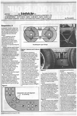
By changing the spring angle and by variations in rubber hardness, a whole range of rubber suspension components can be designed capable of .dealing with a wide range of loads approaching the springs from different directions. Bonding of metal to rubber is stronger than the rubber itself and these components can be placed in shear quite safely.
As can be seen in Figure 1, the suspension consists of an equalising balance beam anchored at its centre to two rubber springs. An axle is located at each end of the beam and torque arms of "A" shape, are mounted in cradles and attached to a pillar in the centre of each axle to take the lateral load— Acceleration and braking torques are also absorbed by the torque arms and balance beams which, between them, ensure positive axle location and eliminate axle wind up and axle hop. The "A" shape torque arms, fitted to an ERF eightwheel tipper is shown at Figure 2. The rubber bushings in the equalising beam centres and ends and in the torque arms, marked A, B, C, D, E, F and G in Figure 3, permit the oscillating movements of the axles without friction or metal to metal contact.
During assembly of these bushes, the rubber is elongated and inserted between the inner and outer metals creating a high pressure on the rubber which prevents slippage when subject to torsional deflections. This design restricts excessive movements but allows sufficient movement to relieve stresses on the metal parts in cornering (see Figure 4).
The two torque rods, together with the equalising beams and connecting parts, make up a parallelogram type linkage (Figure 3). This parallelogram arrangement assures positive axle alignment. Axle centres at the wheels always remain equidistant and therefore parallel.
On turns — Figure 4 the rubber-bushed joints perform another function. Through the elasticity, each axle aligns itse independently on turns. The rubber bushing allow a certair amount of in-and-out moverm from the start to the completic of a turn. This self-alignment feature permits each axle to follow its own natural course more closely. Once a straight line track is resumed, the actic of the bushings "squares off" the tandem so that the leadinc tyres set the tracking pattern f the rear tyres.
For and aft and cross axle articulation is provided throw the rubber components, the combined movement and control of which allows a tote articulation of 12 inches. This high degree of articulation reduces the risk of chassis an body distortion and also ensu continuous contact of the wheels with the ground.