


A Trailer for Transporting Cars
Page 66
If you've noticed an error in this article please click here to report it so we can fix it.
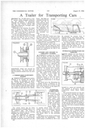
PATENT No. 711,289 shows a twostoried vehicle designed primarily for the transport of motorcars, although the patentee, J. Brockhouse and Co., Ltd., Victoria Works, Hill Top, West Bromwich, envisages other possible uses for it.
Referring to the drawing, the upper floor is guided by rollers running in front guides (1) and others (2) at the rear. The actual lifting is performed by a pair of hydraulic rams (3).
In use, the upper platform is brought down to the position shown at 4 and the cars can then be run on from a low-level ramp. The platform is then hydraulically raised and secured by locking devices. The lower deck can then be similarly loaded from the same ramp.
A TORSION-ROD SUSPENSION SYSTEM
ATORSION-ROD suspension system, said to be suitable for all sizes of vehicle, is described in patent' No. 711,938 (Motor Research Corp., Detroit, Michigan, U.S.A.). A feature of the scheme is that the same torsion rod is used for both the front and the rear wheels on each side of the vehicle.
The vehicle shown has its front wheels mounted on parallel links (1) of the wishbone type. The swing is resisted by a torsion rod (2) running alongside the frame members.
The rear suspension is similarly arranged on links (3), but these are pivoted to swing in a fore-and-aft direction instead of crosswise as at the
A40 front. The links are extended beyond the pivot axis (4) to form arms (5). Each of these is jointed to the rear end of one of the torsion rods. The deflections are in opposition due to the reversal given by the extended rear links. As the back of a vehicle is generally loaded more than the front, extra torsion rods (6) are provided at this end. These terminate on a central cross-member. They are actually anchored on wormwheel sectors mounted on the cross-shaft (7).
A high-reduction gear leads to an electric motor (8), the object of which is to provide a method of adjusting the torsion by winding-up the rods at the touch of a switch.
LONGER LIFE SOUGHT IN VIBRATION DAMPER
A CCORDING to patent No. 712,263, by H. King, 1627 West Fort Street, Detroit, Michigan, U.S.A., the ideal torsional vibration damper would eliminate all torsional vibrations and would have a life equal to that of the engine. A damper claimed to approach this ideal forms the subject of the patent. The drawing shows the device attached to the forward end of a crank shaft (1). It consists of a channelsectioned ring (2) lined with rubber and receiving a disc-shaped inertia mass (3). The rubber is not bonded, but makes friction contact with the channel and the inertia disc. An important feature is that the rubber member is clamped so as to give it the greatest compression at its largest diameter.
The patent gives the dimensions for a damper having a frequency of 150 cycles per second; this is about 52 per cent. of the frequency of the engine for which it was designed.
AUTOMATIC LUBRICATION
PATENT No. 711,957 (Clayton Dewandre Co., Ltd., Titanic Works, Lincoln) deals with devices for providing small but regular charges of lubricant to the various parts of a vehicle. The master pump used is usually driven from the transmission, but if the scheme is required to be adapted to a trailer, special driving arrangements are necessary. The patent refers to this particular problem.
The pump on the tractor is driven by belting from the transmission. The trailer pump is modified so that it can be actuated by vacuum from ti braking system. The master pump, addition to pumping lubricant, ab controls a vacuum line.
At timed intervals it admits vacuu. to the trailer pump and so ensuri regular periodic action thereof. TI patent gives full details of the co. struction of the type of master purr employed.
HYDRAULIC POWER PUMP FOB VEHICLES
IkAANY vehicles are now fitted wi. 'VI hydraulically operated auxiliari• and patent No. 712,338 shows a purr suitable for providing the power. T1 pump uses oil from the gearbox and
located in a space not normally use The patentee is Bendix Aviatic Corporation, South Bend, Indian U.S.A.
The proposed location for the purr is in the space between the clutch ( and the gearbox (2). The transmissic shaft is fitted with a three-thro eccentric sleeve (3) which operates thrt pump plungers contained in a tye bloc (4). The pumping plungers create vacuum on the outstroke for filling, ar on the instroke the oil is forced past one-way valve into a common dischaq duct (5).
The eccentrics do not directly opera the plungers, there being interposed rocker arm with a variable leverag This enables the pump to be set 1 deliver any quantity between full nu put and zero. The control can 1 worked by a pressure-responsive un so that the action becomes entire 'automatic.