


O.H.V. Performance from Side-valve Engines
Page 56
If you've noticed an error in this article please click here to report it so we can fix it.
A Resume of Recently Published Patent SiteafiCations
DATENT No. 601,480 shows combus tion-head improvements which, it is claimed, enable a side-valve engine to equal or exceed the performance of an overhead-valve-type unit of equal capacity. The patentees are W. Marchant, Doone Cottage, Balfour Road, Weybridge, Surrey, and Motosacoche S.A., Geneva, Switzerland.
The drawing shows a plan view of the head with contours taken in three planes, a most informative method of indicating an irregular solid. The exhaust valve is shown at 1; 2 is the inlet and 3 a partial outline of the cylinder bore. The chief feature is the provision of a barrier (4), which is said to reduce the volume of the charge in the vicinity of the exhaust valve, and limit the area subject to burning. The scheme is claimed to permit an increased compression ratio to be safely used and at the same time to reduce detonation. It is ay. improvement on a previous design, disclosed in patent No. 534,077.
FURTHER PROGRESS WITH ROTARY VALVES
THE rotary valve seems to hold a fascination for inventors, and new schemes are continually being evolved.
The latest design appears in patent No. 599,207, which comes from A. Brook, 72, Valley Road, Ipswich.
In this design, which applies to a two-stroke engine, the rotary member is a cylinder having three recesses equidistant from one another as shown. This barrel is lightly nipped between a half-bore in the cylinder head and a bolted-on housing, provided with water-cooling spaces. The hollow space in the centre of the rotor is part of an oil-circulating system, and heat-expansion is said to be negligible on this account. The recesses on the rotor are edged with straight "piston rings" (I) to make a seal, and three sets of circular rings are provided.
In operation, pre-compressed mixture is fed in through port 2 and is carried A38. around and ignited by the plug (3), just as the cylinder port (4) is uncovered. The gases then descend into the cylinder, giving the power stroke, and finally exhaust on the upstroke out of port 5. The exhaust is cut off rather early, so as to provide a measure of cushioning in readiness for the next ignited charge.
The volume of the spaces in the valve is approximately one-tenth of the piston swept volume. As for materials, it is preferred to make the rotor of one of the new self-lubricating irons, the surrounding liner of hardened steel and the sealing strips of cast iron.
A TUBULAR-BACKBONE-CHASSIS VEHICLE
A DESIGN for a vehicle in which the main frame is a central tubular "backbone" is shown, in patent No. 601,711, by H. Page, Alhambra, California, U.S.A. According to the inventor, the chassis will absorb all the twisting stressescaused by running, and the body can therefore be made much lighter than usual.
The drawing shows a plan view of the scheme as applied to a rear-engined car. The central tube has attached to it a rigid cross-member (1) to carry the front wheels, these being independently suspended on coil-spring units and guided by swinging torque-rods (2). Hydraulic shock absorbers of special design assist the coil-spring units.
The rear wheels are similarly suspended, but in this case a rear axle with universally jointed half axles is employed. The central tube is extended by an oval ring (3) to which the engine, transmission and rear axle are attached; this extension can be rapidly removed for replacement by undoing a split clamp (4) around the tube.
The body is carried on crossmembers (5) which are clamped to the tube with interposed rubber sleeves to prevent the transmission of vibrations. Dowel pins are inserted between the damping brackets and central frame member, to prevent the body from turning on the member. A novel feature of the scheme is that the central tube also functions as the petrol tank. AdVantage has been taken to reduce the unsprung weight of the chassis to a minimum.
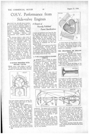
THE TREATMENT OF HOLLOW VALVES
PATENT No. 601,585, from Thompson son Products Incorporated, Cleveland, Ohio, U.S.A., co v ers the processing used in the manufacture of hollow valves. The aim is to produce a valve having increased resistance to fatigue and wear.
The drawing shows the shape of the initial blank, which may be either cast or forged in an alloy containing 14 per cent. nickel, 14 per cent. chromium, 2i per cent. tungsten and 0.35 per cent. carbon, the remainder being iron. The first step is to heat the valve to about 2,050 degrees F. and quench it; this fixes the iron carbide, but leaves the alloy still too soft and large-grained. The next operation is cold working; a mandrel is placed in the bore, and the valve is cold-hammered until the stem is brought down nearly to size and increased in length. The valve is then age-hardened by heat treatment; this time at a temperature of 1,000-1,600 degrees F. for a period of 12 hours; after which it is given the final machining operations.
The patent describes both the operations mentioned and illustrates the tools employed.