


Increasing Resistance to Twist in Chassis Frames
Page 36
If you've noticed an error in this article please click here to report it so we can fix it.
A Résumé of Recently Published Patent Specifications
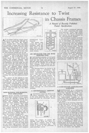
AN all-welded built-up vehicle frame is shown in patent No. 554,430, by Ford Motor Co., Ltd., 88, Regent Street, London:W.1 The chief object is to provide a 'frame that will resist twisting stresses, and so prevent them from being transmitted to the bodywork Only butt-welding is used for .assernbly, and the design is Such that no self-contained stresses are set up.
An accompanying drawing shows an exploded " view of the parts before assembly. A pair of X-shaped L-sectioned pieces (4) is first united by welding and pressed together while being welded to eliminate stress. Two sub-assemblies, the front arm, (5) and the rear pieces (3), each with its crossmember, are next attached to the Xpiece, end pressure being applied during the welding operation. Lastly, the outer channels (1) and the rear cress-member (2) are simultaneously welded together and to the ants (5 and 3). Pressure is again applied during welding, this time in a transverse direction.
The essence of the scheme is that . the. welding pressure is applied first vertically on the X-member, then • longitudinally on the inner channels? and, finally, transversely on the long' members. It is claimed that, owing to the different directions of the forces involved, none of them has any effect on the other two.
NEW MATERIAL FOR SPARKING PLUG INSULATION •
FROM Bendix Aviation Corporation. South Bend, Indiana, U.S.A., comes, in patent No. 554,245, a design for a sparking plug employing, for an insulating and bonding material, a substance which, hitherto, has not been used for the purpose. The plug, generally, is made on accepted lines, mica washers forming the main insulating members but, as is well knbwn, mica is very permeable in one plane,, i.e., between its laminations, and the patent describes a filling material to Close this possible leakage path.
The substance preferred is metaphosphate of sodium, although the metaphosphates of potassium, calcium, strontium or barium are also mentioned. This substance fuses at about 1,300 degrees C., and the plug parts are put under high pressure while the material is in a molten state, the pres, sure being maintained until complete
solidification h a s occurred
The patent also covers the use of synthetic resin for those parts of the plug which are not subject to the maximum stresses.
AIR SEPARATOR FOR USE WITH INJECTED FUEL
I N fuel-injection systems, it is of great importance that all air be extracted from the fuel used, and patent No. 554,445, taken out by C.A.V., Ltd., F. I Evans and W. Nicolls, all of Warple Way, London, W.3, covers an improved design of separator for this purpose.
The drawing shows the device in its ,simplest form; a cylindrical body houses a helically grooved plug (4); rather resembling a coarse-pitched screw. The fuel arrives at the inlet 43) and, after flowing around the thread, makes its exit from port 2. A number of smaller cross-holes (5) connects the lower end of the thread with a central bore (I), which is open at the top. The vortex action of the rotating fuel is said to throw the air bubbles to the central wall, from which they escape through the above-mentioned passages.
A CENTRIFUGALLY ASSISTED CLUTCH
ACLUTCH in which the effort of the driver represents only a fraction of the total operating force, the rest being provided by centrifugal. means, forms the subject of patent No. 554,006, from Borg and Beck Co., Ltd., and L. Godfrey, both of Tachbrook Road, Leamington Spa. The device is called, by the patentees, a semi-centrifugal clutch. Tiler normal withdrawal mechanism is used, comprising the usual pedal-operated thrust ring which presses on -the ends of the fingers and relieves the spring pressure in the well-understood manner.
The centrifugal amplifier is shown in the drawing; it consists of a number of bobweights (3) attached to short arms pivoted about the points 2. Co-operating with the weights are sloping tracks (1) cut in the face of the main pressure plate. During rotation, the centrifugal action of the weights causes them to attempt to roll up the tracks and thereby to increase the engaging pressure. Another scheme shows the centrifugal masses attached to resilient springblades instead of pivoted arms,' the engaging and disengaging effects being approximately similar in both cases.
A CARBURETTER ACCELERATION ENRICHER
A OD IF ICA T ION to a well-known al make of carburetter is shown in patent No. 554,419, by Solex. Ltd., 223-231; Marylebone Road, London, N.W.1, in conjunction with L. -Prat. The improvement consists of an aCeelerating well arranged to discharge into an orifice which normally acts as an air bleed.
Referring to the drawing, fuelflows through the main jet (5) into the centr'al tube (4); here, however, it meets air sucked in through a " bleed " pipe (3) and thus a. rich emulsion is formed which issues into the main venturi. A piston pump (2) is connected with the throttle arm so as to discharge a small quantity of petrol out of a jet (1) into the airLbleed inlet (3); this cuts off the air supply and provides a temporary enrichment of mixture during sudden throttle openings. The -piston of the pump, is, presumably, fitted with a leakage path, So as to prevent it from acting during slow throttle opening, as in such circumstances the enriching device is, of course, not required.