British Progress in Torsion-rod Springing I T is refreshing to fi nd that the pos
Page 56

If you've noticed an error in this article please click here to report it so we can fix it.
sibilities of torsion-bar suspension are not being neglected in this country, as is evidenced by a patent (No. 469,134) from J. Brockhouse and Co., Ltd., and A. Dear, both of Hill Top, West Bromwich. Although shown applied to a special-purpose vehicle, that is, a cabledrum trailer, there is no reason why it should be limited to this use.
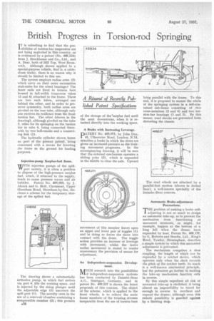
The system employs radius arms (2) which carry on their outer extremities stub-axles for the wheel bearings.* The inner ends are fixed to torsion bars. housed in full-width transverse tubes (3 and 4) attached to the frame. There are two such tubes, arranged one behind the other, and in order to preserve symmetry, both radius arms are pivoted on the rear tube, although only one receives its resilience from the front torsion bar. The other (shown in the drawing), although pivoted on the tube 3, relies for its springing on the torsion bar in tube 4, being connected therewith by two bell-cranks and a connecting link (1).
The hydraulic cylinder shown forms no part of the present patent, being concerned with a means for lowering the frame to the ground for loading purposes.
Injection-pump Surplus-fuel Store.
WITH injection pumps of the spillIT port variety, it is often a problem to dispose of the high-pressure surplus fuel, which, if returned to the supply, tends to cause pressure waves and air bubbles. Patent No. 468,958, by J. Alcock and G. Holt, Claremont, Upper Shoreham Road, Shoreham-by-Sea, diecloses a scheme for the temporary storage of the spilled fuel.
The drawing shows a substantially orthodox pump, in which fuel arrives via port 4, fills the working space, and is injected by the rising plunger until the adjustable edge (3) uncovers the spill port (1). The novelty rests in the use of a reservoir chamber containing a compressible member (2) ; this permits e38 of the storage of thesurplus fuel until the next downstroke, when it is returned directly into the working space.
A Brake with Increasing Leverage.
PATENT No. 468,071, by John Day, 41, Ulleswater Road, London, N.14, describes a brake in which the shoes are given an increased pressure as the brak
ing movement progresses. In the accompanying drawing, it will be seen that the external mechanism operates a sliding yoke (2), which is expanded in the middle to clear the axle. Upward movement of this member forces open an upper and lower pair of toggles (1) and in doing so forces the shoes into contact with the drum. The toggle action provides an increase of leverage with movement, whilst the faster earlier movement is stated to render unnecessary the provision of means for adjustment.
An Independent-suspension Develop ment.
NAUCH research into the possibilities /Vlof independent-suspension systems has been conducted by Daimler-Benz A.G., Stuttgart, Germany, and in patent No. 469,237 is shown the latest proposals of this concern. The object of the scheme, which is applied to the front wheels, is to relieve the main frame members of the twisting stresses inseparable from the use of torsion bars lying parallel with the frame. To this end, it is proposed to mount the whole of the springing system in a self-contained sub-frame consisting of two cross-members (2 and 4) and two torsion-bar housings (1 and 3). By this means, road shocks are prevented from distorting the chassis.
The road wheels are attached by a parallel-link motion (shown in dotted lines), a well-known speciality of the Daimler-Benz concern.
Automatic Brake-adjustment Precautions.
T"problem of making a brake selfadjusting is not so much to design an automatic take-up, as to prevent the mechanism from functioning at unwanted moments, as might, for example, happen at the bottom of a long hill when the drums have expanded by heat. Patent No. 469,177, by G. Roberts and Bendix, Ltd., King's Road, Tyseley, Birmingham, describes a simple system by which this unwanted adjustment is prevented.
The mechanism comprises a shoe coupling, the length of which can be expanded by a ratchet device, which operates only when the slack exceeds the pitch o,f the ratchet teeth. So much is a well-known mechanical principle, but the patentees go farther in making the take-up mechanism function only in reverse.
By this simple expedient all risk of unwanted take-up is abolished, it being almost an impossibility to travel far enough in reverse to overheat and expand the drums ; although even this remote possibility is guarded against by a limiting stop.


