


TOLER
Page 42
Page 43
Page 44
Page 45
If you've noticed an error in this article please click here to report it so we can fix it.
.A\ C E S
what are the
rrnissible limits?
RULE-OF-THUMB methods are not suitable for precision work, and for efficient fleet maintenance they must be replaced by something
much more definite and accurate. The term is most usually applied to the taking of measurements of some form or another. For example, a workman will spit on a bit of hot metal to ascertain its temperature, or run his eye along a shaft to see if it be straight.
The exact method, in the one case, is to heat the part in a pyrometer-controlled furnace, and, in the other, is to rotate the shaft between centres against a dial gauge indicating to fine limits.
Besides the method of testing, the-limiting degree of inaccuracy requires to be known, and there are few maintenance engineers, even amongst experienced and well-qualified men, who have never been in doubt as to whether the wear of a part, for instance, was sufficient to justify its renewal or whether it would be safe to continue with it in use.
For the help and guidance of all who are responsible for the satisfactory functioning of commercial vehicles.
we have compiled a list of tolerances, which covers nearly all the wearing parts of a modern chassis. The values given will be found to be generally correct, but to practically everything there are exceptions, and in certain cases modifications will need to be made.
Pistons, for example, have different clearances at the top, between the rings and at the skirt; moreover, the various types differ markedly in this respect. Alloy specifications also have a marked bearing on clearance, and where makers' instructions are available, these should obviously override our figures.
Again, ball and roller bearings are usually offered with, at least, two clearances, according to the purpose for which they are intended, so that our values for these must be taken as only a guide, which, whilst perfectly serviceable, may not afford the utmost efficiency in the functioning of the component affected.
However, if the figures tabulated on these 'pages he followed exactly, we feel that we are safe in saying that the engineer employing them cannot go far wrong.
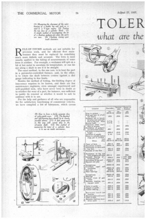
From the accompanying sketches, it will be seen that the instruments used for most of the measurements are calliper and internal micrometers, a telescope gauge,
a dial or clock gauge, feelers, a straight-edge and a surface plate. The methods illustrated can be adapted for all the operations referred to only in the tables.
Considering first the piston group, the clearance of the piston in the cylinder is easily measured with the feeler gauge. The values given must be multiplied by the diameter of the piston in inches, and, of course. the figures differ considerably for cast-iron and aluminium-alloy pistons. Some special-alloy pistons can be fitted with a skirt clearance as low as .001 in., whilst, with the Invar strut, it may be even less.
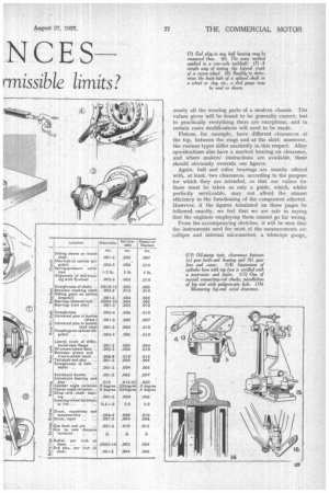
Parallelism of gudgeon-pin bore and crown is measured with a straight-edge passed through the hole, with the piston standing on its crown on a surface plate. The two ends of the straight-edge are then tested, as close to the piston as possible, with a clock gauge, the pedestal of which is slid over the surface plate. Similarly, the distances between bore and crown (compression height) of all the pistons of the engine are compared. A simple pair of scales is all that is required for comparing their weights.
Of Great Importance.
Ring-in-groove clearance is measured with a feeler, and so is the gap, the latter operation being performed with the ring squarely in the cylinder, to which position it is brought by pushing it in with the piston.
To test the fit of a new gudgeon pin, assemble the piston and connecting rod on it, then with a spring balance hooked to the large end of the rod, find the pull required to move the rod while the piston is held. We give figures (in lb.) for a floating pin in an alloy piston and for a pin in bronze bushing. This test obviously applies only to new parts; for part-worn ones the clearances are measured by micrometer and telescope gauge in the manner described later in connection with big-end roundness.
Another, test for parallelism is between the big-end and gudgeon-pin bearings. The best means for doing this is an aligning fixture, used with the clock gauge. The rod is bolted on to a dummy crankpin, and the distances from this to the two ends of a dummy gudgeon pin are then compared.
The Telescope Gauge.
The roundness of the big-end bearing is investigated with the telescope gauge and micrometer. For those not familiar with the former, it consists of a measuring piece held like the cross of a T in a straight handle which forms the upright. The cross-piece comprises two tubes, with closed outer ends, one telescoping in the other, and housing a spring that tends to push them apart. 'The handle incorporates a screw device that locks the tubes together in any position.
This gauge is set to the bore of the bearing by inserting it and then locking it, whilst the measurement is subsequently obtained with the micrometer.
Certain engines with V-type cylinder arrangement have forked big ends incorporating an outer bearing. We give the clearance for these, and show the method of measuring it, which is done as above with the telescope gauge and micrometer. It will be noted that a minimum value is given as well as a maximum. The end play of the big end on its crankpin is easily checked with a feeler gauge.
There are several important points, in connection with the cylinder block, to be investigated. Bore wear or internal taper is easily ascertained with an inside micrometer. Roundness may be checked in the same way or by means of the dial gauge. To measure 3310 inaccuracies in the squareness of the cylinder walls with the top face, a protractor is employed and used in conjunction with a set of feelers. The last-named and the straight-edge are required to measure errors in the flatness of the top face.
Main Crankshaft Tests.
Coming now to the crankshaft, the chief tests are straightness, crankpin and main-journal taper and ovality, and end play. To conduct the first, the shaft should be mounted between centres or on rollers, and the clock gauge brought into contact with it at the centre and other points. Whilst a high degree of truth is expected, quite a relatively large error is tolerated by reason of the length of the part. '
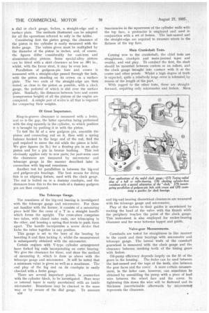
With regard to the other tests, these are straightforward, requiring only micrometer and feelers. Main and big-end-bearing diametrical clearances are measured with the telescope gauge and micrometer.
Play of the valves in their guides is ascertained by rocking the head of the valve with the thumb while the periphery touches the point of the clock gauge. This instrument is also employed for rocker-bearing clearance and for wear between tappet and guide.
Valve-gear Measurements.
Camshafts are tested for straightness in like manner to the crank and their bearings with micrometer and telescope gauge. The lateral truth of the camshaft gearwheel is measured with the clock gauge and the clearance between meshing teeth of the timing gears with feelers.
Oil-pump efficiency depends largely on the fit of the gears in the housing. The feeler can be used between the last-named and the tops of the teeth, also between the gear faces and the cover. A more certain measurement, in the latter case, however, can sometimes he obtained by assembling the pump with a piece of lead wire between the wheel face and the cover. In tightening this down the wire will be flattened and its thickness (ascertainable afterwards by micrometer) represents the clearance.
Slackness of the pumpsha ft bearing is given by the clock gauge, whilst the feeler will show back-lash in the skew-drive teeth.
Passing on from the power unit, we have next to consider the transmission. An important preliminary check is for the alignment of the flywheel face with the bell housing; this is done with the clock gauge. The same instrument can conveniently be employed for ascertaining the spline clearance of the hub of the clutch disc. For comparing spring pressures, a special device is desirable.
For the four main gearbox tests the dial gauge is needed. Back-lash between teeth and on splines is measured by holding one part and rocking its fellow against the point, while noting the dial reading. The operations of investigating diametrical and axial bearing wear are similarly performed.
Propeller and axle shafts are tested for straightness like the crankshaft and splines, as already described. The tolerances are given in the tables. For the lateral truth of the differential-case flange and the back of the crown wheel, use the clock gauge. End play of the tailshaft can also be examined with this instrument, carrying out the test, with the differential assembly removed. For play between crown wheel and pinion teeth, employ the feeler gauge.
Important steering-gear tests and the instruments needed are as follow: Swivel pin and bushing, micrometer and telescope gauge; swivel-pin end play, feelers; drop-arm shaft bearing, micrometer and telescope gauge.
Methods of making the other tests, referred to in the tables, need not be outlined, except, perhaps, those for the brake drums, which are best done with a special appliance, but can be performed with the clock gauge, using the hub, or drum centre, as basis. Finally, this useful instrument can be employed for all ball and roller bearings, shafts, etc.
In conclusion, we wish to make acknowledgment to our transatlantic contemporary, the Commercial Car Journal, from which the majority of the tolerance values published was obtained.