


A Morris-Commercial Exhaust-pipe Connection
Page 70
If you've noticed an error in this article please click here to report it so we can fix it.
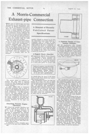
MHE form of exhaust-pipe connection described in the specification (No. 315,985) of Morris Commercial Cars, Ltd., and W. W. Hamill, is intended to effect two useful purposes—namely, to provide a means whereby an exhaust pipe can be connected to an engine pipe, with satisfactory results, although the parts may not be in accurate alignment, and to prevent the hot gases from burning away the thin pipe by being allowed to come into contact with its walls while still in the form of flame.
The first object is secured by bellingout the end of the pipe so that it forms a follow which can accommodate a truncated spheroidal ring. This bears against a washer, which separates it from the flat flange formed on the end of the pipe leading from the engine. By means of the spheroidal construction a considerable error in alignment may exist, but a gastight joint can be obtained.
The second objet is achieved by forming the ring with a tapering interior, so that the gases are diverted towards the centre of the pipe, thus preventing burning.
A joint which had a truncated spheroidal projection and a recess to receive it was employed for many years in the Commer Car and found to be per
fectly satisfactory. In this instance, however, the pipe leading from the engine was recessed by means of a rosecutter and a projection was formed on the flange attached to the long pipe. No jointing washer was needed and the accurate alignment of the pipe was negligible.
Absorbing Periodic Engine Vibrations,
TO absorb the periodic vibrations and
noises produced by engines is the object of the patented invention of H. V. Reed, of Chicago, which is described in specification No. 315,748. The device consists of a clutch plate, to which is fixed the frictional discs, but instead of the plate being rigidly attached to its boss it is freely mounted so that partial rotary movement is permitted, but it is at all times held concentric with its boss. A triangular or some irregular space is formed in the plate and a similar, but c48
smaller, triangle is formed on its boss, the intervening space being filled by a triangular ring of rubber or other cushioning material, by which means a slight yield in the drive is obtained. A sectional view which we publish shows the means used for preventing the plate from assuming an angle with its shaft, the housing of the rubber ring forming a means for steadying it.
A Bugatti Shock Absorber.
IN patent No. 298,193 Ettore Bugatti, of Bas-Rhin, France, describes the application of a shock absorber, not only to deaden the vertical movement of an axle, hut to deaden the tendency of a front axle partly to revolve with its wheels when the shoes in the brake drums on the front wheels are reasonably heavily operated.
The specification points out that the torsion of a front axle due to brake reaction may produce pronounced vibration of the springs, which is objectionable. To prevent this, frictional or hydraulic shock absorbers fixed to the front axle are provided, the tail being anchored to an extension from the dumb iron. A slot and roller are shown, but other means for anchorage, such as links, may be employed. A Japanese Design of Combustion Chamber.
IN his specification (No. 315,684)
Rennosuke Kondo, of Tokio, describes a new form of combustion head, which is claimed to prevent preignition and to increase the efficiency of an engine. The design provides for a head having a narrow passage in which the sparking plug is mounted ; this course leads to a still narrower passage communicating with a chamber.
The specification points out that on the compression stroke, and even when the stroke is completed, there is always a movement of the mixture in the passage in which the sparking plug i,s mounted. As a result, there is moving gas passing the points of the plug, as, owing to the very small aperture leading to the extra chamber, the gas must take an appreciable time before the chamber can become filled to the same pressure as that of the main chamber formed by the cylinder. The effect of the movement of the gas is not made very clear in the specification; the following passage, however, throws some light on the subject:— "With the arrangement according to the present invention, at ignition and just prior thereto, even if the mixture he highly compressed, a comparatively low-pressure part is formed in the neighbourhood of the igniting device and the mixture is ignited while it is moving past the ignition device away from the cylinder. Therefore, the occurrence of premature ignition can he prevented and, consequently, the efficiency of the engine is increased." At very high speeds it would appear that the movement of the gases cannot take place ; consequently, the engine works in the usual manner. The small automatic valve in the upper chamber is for the introduction of any fluid desired further to prevent detonation.