


IMPROVED BRAKE EQUIPMENT for Heavy Commercial Motors
Page 52
Page 53
If you've noticed an error in this article please click here to report it so we can fix it.
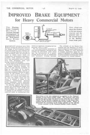
The Westinghouse Company Markets a Vacuum Storage Arrangement in Conjunction with its Well-known Servo Brake System.
T M PORTANT advances have been J_ made during the past few years in the design of servo-assisted brakes of several k.inds for road vehicles, far greater braking efficisncy having become necessary with the increase of speed at which heavy loads are transported. Oil-pressure, pneumaticpressure (both positive and negative) and mechanical servo systems have been developed, each type having certain advantages.
In the kind of vacuum-servo brake in which the suction is derived from the engine induction system, the power is only directly available so long as the engine is in motion. This is a disadvantage, because it sometimes happens, during the application of the., brakes on a heavy vehicle, such as an articulated sixwheeler or a tractor and trailer outfit, that the engine stops and the driver is obliged to resort to his auxiliary, mechanically operated brake equipment which, generally speaking, is not nearly so powerful. , To provide against this circumstance, the Westinghouse Brake and Saxby Signal Co., Ltd., of 82, York Road, London, N.1, announces that it is putting on the market a vacuum reservoir outfit, in conjunction with
which an ingenious charging and application valve is used.
We are particularly interested to note the development, because in this journal we advocated, some years ago, the introduction of a powerstoring device for use in conjunction with pneumatic braking systems. The attitude of the Royal Commission and the Ministry of Transport in regard to speed limits for the different classes of road machines is largely dependent upon the degrees of efficiency of reliable makes of power-assisted braking gear which are adopted by chassis makers.
In the new Westinghouse system a vacuum reservoir of suitable size, say, 3 ft. 6 ins, long and 8-10 ins, in diameter, and having a capacity sufficient to care for several applications of the brake, is conveniently housed on the chassis, the vacuumcharging and brake-application valve, shown in the accompanying drawings, being bolted to a flange at one end of it.
Reference to the accompanying drawings will explain how the nipple (13) is connected by piping to the engine induction system and the nipple (C) is similarly connected to the driver's control valve. When the engine is started air is exhausted from the chamber (D) and, at a slower rate, by the small opening (I) from the large reser voir. The partial vacuum produced in the chamber (D) causes the diaphragm (E) to des cencl and open the valve (F), thus establishik corn ramification by the connections (13 and C) between the engine induction pipe and the driver's control valve. At the same time the valve (G) is seated, thus closing the connection between the reservoir and, the control valve. f
With the engine continuing to ran, air is gradually ,exhausted from the reservoir and, at the same time, by way of the small passage (H), from the upper side of the diaphragm (E). So 80011 as the degree of vacuum above the diaphragm equals that below it, the diaphragm automatically moves upward, opening valve (0) and thus providing communication between the driver's control valve and the reservoir, whilst communication between the engine induction system and the driver's control valve is restricted by the valve (F). It will be seen that if the engine shopld stop, the degree of Absorbing Tappet Wear and Noise.
A special and improved device that is claimed to absorb the wear and noise of tappets is now being marketed by Mr. A. H. F. Pen, of Anti-Taps, 46, Oxford _Road, Acocks Green, Birmingham.
This appliance is intended to be fitted between the valve stem and the tappet head. It consists of a spiral metal ring having superimposed centre pieces, the upper part of which is countersunk to receive the valve stem. The method of fitting the device is as follows :—Adjust the tappet until thi
negative pressure in chamber (D) will become less than that above the diaphragm (E). The diaphragm will, therefore, rise and close the valve (F), thus cutting off communication between the induction system and the control valve, and opening valve (G) wide. It thus places the control valve in direct communication with the reservoir, the partial vacuum in which becomes available for operating the brake.
To explain the action briefly, the valves (F) and (0) move in such a way as to open, more or less, the communication between the driver's control valve and either the reservoir or the engine induction pipe, according to which contains the higher degree of vacuum. It follows that when actuating the brake while the engine is running both these sources of power are available, and the ingenious charging and application valve is so designed, that the degree of power remains practically constant in spite of variations in the engine speed.
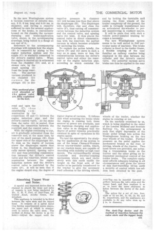
We had the opportunity for studying the application of the system to one of the latest Chenard-Walcker 10-ion tractor-trailer outfits, which, as our readers know, are capable of travelling with stability at high road speeds. The extraordinarily strong turntable and drawbar-coupling mechanism which are used exclusively with this outfit enable the weight on the front axle of the trailer to be partially transferred to the tractor to give the necessary , road adhesion to the driving wheels, and by locking the turntable am] raising the front wheels of the trailer completely off the ground, the outfit is virtually transformed into an articulated six-wheeler to permit manoeuvring in confined spaces.
It will be plain that with such a• vehicle power-assisted braking becomes a necessity.
The new Westinghouse system seems to be well suited to this particular make of machine. The brake cylinder is fixed to the trailer frame, a flexible coupling of the type familiar on railway coaches being employed in the pipe between the cylinder and the driver's control valve. The powerful vacuum servo brake can thus be applied to the rear wheels of the trailer, whether the engine be rotating or not.
On the machine examined by us, , which is being supplied to the order of the London Midland and Scottish Railway Co., the arrangement is such that slight depression of the brake pedal brings into action the Westinghouse braking on the two rear wheels of the trailer. Further pressure on the pedal applies the mechanical brakes on the rear, or driving, wheels of the tractor. Two hand levers are provided, one actuating a transmission brake on the tractor and the other giving an independent mechanical control of the trailer brake. The complete equipment affords adequate braking in all circumstances and gives the driver of this fast-travelling -10-ton outfit a security of control which has seldom been obtained in the past.
Anti-Tap can be inserted (pressed together) between the valve stem and the tappet bead, and then readjvst it so as to leave the same clearance as before between the leaves of the AntiTap.
The prices for a set of two, four, eight or 12 are fid., 1s. 6d., 2s. ad. and 4s. respectively, and the appliances are available to fit any valve stem up to in. in diameter.