The compression ignition engine 10
Page 69

If you've noticed an error in this article please click here to report it so we can fix it.
WHEN DPA and -in-line" injection pumps are serviced, two main tests, "calibration" and "phasing" have to be done. -Calibrationis the test which shows whether each cylinder of the engine to which the pump is to be fitted is receiving the same ,correct quantity of fuel at all ,engine speeds.
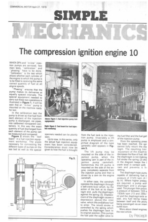
"Phasing" ensures that the pump makes its deliveries at equally spaced intervals. The special equipment needed to carry out these two operations is illustrated in Figure 1. It will be seen that an "in-line" pump is mounted on the machine ready for test.
In the calibration test the pump is driven so that fuel from each element of the injection pump is discharged, via pipes, into calibrated transparent containers. In this way the exact quantity of fuel discharged from each element of the pump can be measured and compared.
Figure 2 shows the "tool boardin a fuel injection equipment workshop. The pipes necessary for connecting the different types of pumps on the test bed as well as the special
spanners needed can be plainly seen.
Up to now, in this series, only the actual fuel injection equipment has been considered. Consideration must now be given to how the fuel is brought
from the fuel tank to the injection pump. Invariably a lift pump is employed and a simplified diagram of the type generally used appears in Figure 3.
The lift pump may be mounted on the side of the injection pump, when the operating cam is part of the injection pump camshaft. Sometimes the lift pump is mounted on the side of the engine, completely separate from the injection pump and then is driven by a cam on the engine camshaft.
In either case, the camshaft operates the diaphragm through a bell-crank lever which, by the action of the fork at its diaphragm end, pulls the diaphragm against the spring (1). Displacement of the diaphragm causes a depression above the inlet valve, which lifts and allows fuel to enter. The return stroke is controlled by the spring which pushes the diaphragm back to its original position. This pumps the fuel past the outlet valve to
the fuel filter and the fuel gall of the injection pump.
Once the operating press has been reached, the spr cannot fully return the dia ragm. The resulting limi movement of the diaphra decreases the flow of fuel. WI the diaphragm is not making full stroke the spring (2) sho in the diagram keeps the I crank level in contact with cam and prevents it fr, rattling.
The diaphragm-type pumj capable of delivering fuel a pressure of 31kN / sqm (4.l sq in). Where higher pressu are required, a pump with diaphragm and a plunger used. The plunger then provit a pressure of between 103 a 193kN/sqm (15 and 281b/ in) and the diaphragm acts a! seal, any fuel being trapp between itself and the plunc being scavenged via an interi outlet duct.
More about diesel engines the next article.
by Precept(


