


Improvements in Hydraulic Couplings
Page 36
If you've noticed an error in this article please click here to report it so we can fix it.
A &mind of Patent Specifications That Have Recently Been Published
Toimprove the efficiency of a coupling of the hydraulic type is the object of a modified design shown in
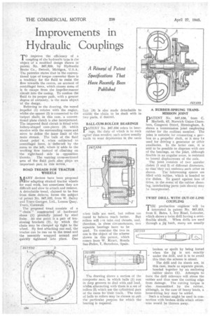
• patent No. 567,559, by Hydraulic Brake Co., Detroit, Michigan, U.S.A. The patentee states that in the conventional type of torque converter there is . a tendency for the fluid to resist the flow towards the centre, on account of centrifugal force, which causes some of it to escape from the .impeller-runner circuit into the casing. To confine the fluid to its proper path, with a greater degree of certainty, is the main objsct • of the design.
• Referring to the drawing, the vaned • impeller (1) rotates with the engine, • whilst the runner (2) is connected to the
• -output shaft; in this case, 'a, conventional plate clutch is also incorporated. The improved fluid circuit is fitted with kidney-shaped core,pieces (3), which revolve with the surrounding vanes and serve to define the inner limit 'of the main stream. The bulk of the fluid about point 9, . when subjected to centrifugal force, is defleeted• by the cores to the left, where it adds to the working flow instead of climbing OR
• the right-hand side in opposition thereto. The varying cross-sectional area of the fluid path also plays an important part in this action, ROAD TREADS FOR -TRACTOR . . WHEELS
MANY devices have been proposed for adapting straked tractor wheels for road work, but sometimes they are difficult and slow -to attach-and remove. A detachable. 'tread; claimed to be free from thege .defects,: forms —the Subject of patent No, 567,532, from W. Bailey and Truro Garages, Ltd., Lemon Quay, Truro, Cornwall,.
The proposed tread consists of a " chain" constructed of hardwood shoes (1) pivotally joined by steel links. At one point is a pair of tensioning brackets (2), by which the: chain may be clamped up tight to the wheel. By first attaching one end, the; • tractor can be run on to the tread and the assembly wrapped around and • quickly tightened into place. One link (3) is also made detachable to enable the chain to be dealt with in two' parts, if desired.
BALL.CUM-ROLLER BEARINGS
DATENT No. 567,556 refers to bearings, the duty of which is to rock Viler than revolve; such action usually tends to wear depressions in the laces
when balls ate used, but rollers are
found to behave much better. But rollers will rot take. end thrusts, and, therefore, in these circumstances, two separate bearings have to be used. To combine the two in Ono is the object of the scheme shown in this patent, which comes from W. Ricart, Ronda San Pedro, 7, Barcelona, Spain.
The drawing shows a section of he composite race, in which balls (I) run in deep grooves to deal with end load, whilst alternating with them is a set Of rollers (2) which-use the cylindrical part of the races for 'their. track, The ratio of balls to rollers may be chosen to suit the particular purpose for which the bearing is required.
A RUBBER-SPRUNG TRANSMISSION JOINT IjATENT No. 567,536, from Macbeth, 67, Norwich Union Chambers, Congreve Street, Birmingham, 3, shows a transmission joint employing rubber for the resilient member. The joint is suitable for connecting a gewbox to a propeller shaft, or it may to used for driving a generator or other auxiliaries. In the latter case, it is Said to be possible to dispense with one of the bearings, as the joint, although flexible in an angular sense, is resistant to lateral displacement of the axis.
The joint consists of two annular disheS (1 and 2) of different diameters, so that'they Can embrace each other as
shown. Theintervening spaces are filled with tubber, Which is bonded to the dishes. To guard against loss of drive, in the eventof the rubber shear:. In g, interlocking Parts (net 'shown) may
he incorporated. . TWIST DRILL WITH OUT•OF-LINE COUPLING •
THE production engineer will he interested in patent No. 567,553, from E. Bates, I, Ivy Road, Leicester, which shows a twist drill having a semiflexible shank. When drills are used through a jig bush, many are usually
C.
broken or spoilt by being forced when the jig is not exactly under the drill, and it is to avoid this that the scheme is aimed.
The drill and its shank are, in this case, made as separate pieces, bonded together by an enclosing rubber sleeve (1). Attempts to force the drill sideways will stress the rubber and thus save the cutting edge from damage. The cutting torque is also transmitted., by the rubber, altheush, in the case of heavy loads, a loose-fitting key may be added.
Such a scheme might be used in con-. nection with broken drills which otherwise would be thrown away.