 1
1 2
2 3
3 4
4 5
5 6
6 7
7 8
8 9
9 10
10 11
11 12
12 13
13 14
14 15
15 16
16 17
17 18
18 19
19 20
20 21
21 22
22 23
23 24
24 25
25 26
26 27
27 28
28 29
29 30
30 31
31 32
32 33
33 34
34 35
35 36
36 37
37 38
38 39
39 40
40 41
41 42
42 43
43 44
44 45
45 46
46 47
47 48
48 49
49 50
50 51
51 52
52 53
53 54
54 55
55 56
56 57
57 58
58 59
59 60
60 61
61 62
62 63
63 64
64 65
65 66
66 67
67 68
68 69
69 70
70 71
71 72
72 73
73 74
74 75
75 76
76 77
77 78
78 79
79 80
80 81
81 82
82 83
83 84
84 85
85 86
86 87
87 88
88 89
89 90
90 91
91 92
92 93
93 94
94 95
95 96
96 97
97 98
98 99
99 100
100 101
101 102
102 103
103 104
104 105
105 106
106 107
107 108
108 109
109 110
110 111
111 112
112 113
113 114
114 115
115 116
116 117
117 118
118 119
119 120
120 121
121 122
122 123
123 124
124 125
125 126
126 127
127 128
128 129
129 130
130 131
131 132
132 133
133 134
134 135
135 136
136 137
137 138
138 139
139 140
140 141
141 142
142 143
143 144
144 145
145 146
146 147
147 148
148 149
149 150
150 151
151 152
152 153
153 154
154 155
155 156
156 157
157 158
158 159
159 160
160 161
161 162
162 163
163 164
164 165
165 166
166 167
167 168
168 169
169 170
170 171
171 172
172 173
173 174
174 175
175 176
176 177
177 178
178 179
179 180
180 181
181 182
182 183
183 184
184 185
185 186
186 187
187 188
188 189
189 190
190 191
191 192
192 193
193 194
194 195
195 196
196 197
197 198
198 199
199 200
200 201
201 202
202 203
203 204
204 205
205 206
206 207
207 208
208 209
209 210
210 211
211 212
212 213
213 214
214 215
215 216
216 217
217 218
218 219
219 220
220 221
221 222
222 223
223 224
224 225
225 226
226 227
227 228
228 229
229 230
230 231
231 232
232 233
233 234
234 235
235 236
236 237
237 238
238 239
239 240
240 241
241 242
242 243
243 244
244 245
245 246
246 247
247 248
248 249
249 250
250 251
251 252
252 253
253 254
254 255
255 256
256 257
257 258
258 259
259 260
260 261
261 262
262 263
263 264
264 265
265 266
266 267
267 268
268 269
269 270
270 271
271 272
272 273
273 274
274 275
275 276
276 277
277 278
278 279
279 280
280 281
281 282
282 283
283 284
284 285
285 286
286 287
287 288
288 289
289 290
290 291
291 292
292 293
293 294
294 295
295 296
296 297
297 298
298 299
299 300
300 301
301 302
302 303
303 304
304 305
305 306
306 307
307 308
308 309
309 310
310 311
311 312
312 313
313 314
314 315
315 316
316 317
317 318
318 319
319 320
320 321
321 322
322 323
323 324
324 325
325 326
326 327
327 328
328 329
329 330
330 331
331 332
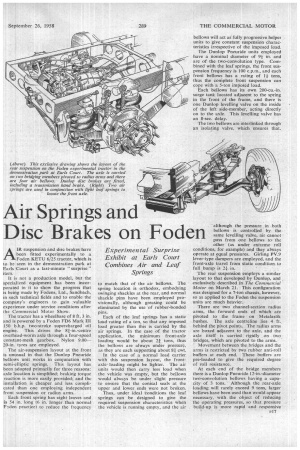
332 Air Springs and Disc Brakes on Foden
Page 131
Page 132
If you've noticed an error in this article please click here to report it so we can fix it.
AIR suspension and disc brakes have been fitted experimentally to a Foden KETU 6/25 tractor, which is to be seen in the demonstration park at Earls Court as a last-minute " surprise " item.
It is not a production model, but the specialized equipment has been incorporated in it to show the progress that is being made by Fodens, Ltd., Sandbach, in such technical fields and to enable the company's engineers to gain valuable experience under service conditions after the Commercial Motor Show.
The tractor has a wheelbase of 8 ft. 3 in. and is powered by a Foden FD6 Mark III 150 b.h.p. two-stroke supercharged oil engine. This drives the 81-in.-centre overhead-worm axle through a four-speed constant-mesh gearbox. Nylon 9.0020-in. tyres are employed.
The air-suspension layout at the front is unusual in that the Dunlop Pneuride bellows unit works in conjunction with semi-elliptic springs. This layout has been adopted primarily for three reasons: axle location is simplified; braking torque reaction is more easily provided and the installation is cheaper and less complicated than one employing independent front suspension or radius arms.
Each front spring has eight leaves and is 54 in. long (6 in. longer than normal F-Jden practice) to reduce the frequency to match that of the air bellows. The spring location is orthodox, embodying swinging shackles at the rear, and normal shackle pins have been employed provisionally, although greasing could be eliminated by the use of rubber-bonded pins.
Each of the leaf springs has a static Iohd rating of a ton, so that any imposed load greater than this is carried by the air springs. In the case of the tractor application, the minimum front-axle loading would be about 24 tons, thus the bellows are always under pressure, as they are each supporting about 81 cwt.
In the case of a normal load carrier with this suspension layout, the frontaxle loading might be lighter. The air units would then carry less load when the vehicle was empty, but the bellows would always be under slight pressure to ensure that the conical seals at the upper and lower ends were not broken.
Thus, under ideal conditions the leaf springs can be designed to give the required suspension characteristics when the vehicle is running empty, and the air bellows will act as fully progressive helper units to give constant suspension characteristics irrespective of the imposed load. The Dunlop Pneuride units employed have a nominal diameter of 9i in. and are of the two-convolution type. Combined with the leaf springs, the front suspension frequency is 100 c.p.m., and each front bellows has a rating of I I tons, thus the complete front suspension can cope with a 5-ton imposed load.
. Each bellows has its own 200-cu.-in. surge tank located adjacent to the spring in the front of the frame, and there is one Dunlop levelling valve on the inside of the left side-member, acting directly on to the axle. This levelling valve has an 8-sec. delay.
The two bellows are interlinked through an isolating valve, which ensures that,
although the pressure in both bellows is controlled by the • same levelling valve, air cannot pass from one bellows tothe other (as under extreme. roll conditions, for example) and they always operate at equal pressures. Girling PV.9 lever-type dampers are employed, and the front-axle travel from static condition,to full bump is 21 in.
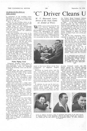
'The rear suspension employs a similar layout to that developed by Dunlop, and . exclusively described in The Commercial Motor on March 21. This configuration was designed for a 7-ton chassis, however, so as applied to the Foden the suspension units are much heavier.
There are two channel-section radius arms, the forward ends of which are pivoted to the frame on Metalastik bushes. The axle centreline .lies 4 ft.. behind the pivot points. The radius arms are boxed adjacent to the axle, and the axle itself, is carried rigidly on two bridges, which arc pivoted to the arms.
Movement between the bridges and the arms is restricted by two rubber anti-roll buffers at each end. These buffers are pre-loaded to give the required degree of roll resistance.
At each end of the bridge members there is a DunlopPneuride 12-in.-diameter two-convolution bellows having a capacity of 3 tons. Although the rear-axle loading will rarely exceed 9 tons, larger bellows have been used than would appear necessary, with the object of reducing the operating pressures, so that pressure build-up is more rapid and respOnsive to. movement of the levelling valves. Obviously, it is quicker to increase pressure from 40 p.s.i. to 50 p.s.i. than from 90 p.s.i. to 100 p.s.i.
There are two levelling valves at the rear axle, mounted inside the frame side members and two Girling dampers.
Surge tanks are not incorporated, because the bellows capacity is such that each pair gives the required frequency of 115 c.p.m., without the additional surge-tank capacity.
The total available axle stroke of the present installation is 5.1in., this being limited by the 200 p.s.i. maximum pressure allowable inside the air bags under full-bump conditions. If surge tanks are fitted,however, the maximum bag pressure will be lower and the axle travel could be increased correspondingly.
The suspension is fed from a separate main reservoir, which, like the braking reservoir, has a protection valve. The two systems, although interlinked so that the suspension tank is fed from the brake tank, become independent in the event
of failure of either system. A watercooled Tu-Flo 400 air compressor has an output rating of 7.5 Cu. ft. The maximum air pressure is 105 p.s.i., but the maximum working pressure at the rear bellows in service will be about 70 p.s.i.
Nylon Piping Used
Polypenco Nylaflovv nylon piping is used extensively in the installation, but reinforced-rubber hoses are employed between the levelling valves and the bellows units.
Fodens hope that their experiments with air-springs will allow them to make reductions in the weight of the chassis because of the lower stressings.
Dunlop disc brakes are used at both axles and for the transmission hand system. The axle discs are 151 in. in diameter and 11 in. thick, and are interchangeable between hubs.
Each front brake has a single twin-calliper unit, each calliper containing four friction segments actuated by four 3-in.diameter hydraulic pistons.
A li-in.-diameter master cylinder actuates the front brakes, the maximum
line pressure being 1,200. and the master cylinder is mounted in conjunction with a Clayton Dcwandre type 30 air-pressure actuator, controlled. by a 131 valve with treadle pedal.
At the rear there are two twin-calliper units per wheel, each with four pads, and four 31-in.-diameter . pistons. The Lf-in.-diameter master cylinder works on a separate circuit to the front brakes and has its own air-pressure actuator.
The friction pads at all wheels are interchangeable and are ITV, in. thick, 4in. deep, and 311 in. long. A pair of pads can be changed simply by removing one bolt.
The transmission disc is the same size as the wheel discs, but the mounting is different, so it is not interchangeable. A single twin-calliper unit is actuated by cable from a Foden variable-leverage hand-brake lever.
Ft