 1
1 2
2 3
3 4
4 5
5 6
6 7
7 8
8 9
9 10
10 11
11 12
12 13
13 14
14 15
15 16
16 17
17 18
18 19
19 20
20 21
21 22
22 23
23 24
24 25
25 26
26 27
27 28
28 29
29 30
30 31
31 32
32 33
33 34
34 35
35 36
36 37
37 38
38 39
39 40
40 41
41 42
42 43
43 44
44 45
45 46
46 47
47 48
48 49
49 50
50 51
51 52
52 53
53 54
54 55
55 56
56 57
57 58
58 59
59 60
60 61
61 62
62 63
63 64
64 65
65 66
66 67
67 68
68 69
69 70
70 71
71 72
72 73
73 74
74 75
75 76
76 77
77 78
78 79
79 80
80 81
81 82
82 83
83 84
84 85
85 86
86 87
87 88
88 89
89 90
90 91
91 92
92 93
93 94
94 95
95 96
96 97
97 98
98 99
99 100
100 101
101 102
102 103
103 104
104 105
105 106
106 107
107 108
108 109
109 110
110 111
111 112
112 113
113 114
114 115
115 116
116 117
117 118
118 119
119 120
120 121
121 122
122 123
123 124
124 125
125 126
126 127
127 128
128 129
129 130
130 131
131 132
132 133
133 134
134 135
135 136
136 137
137 138
138 139
139 140
140 141
141 142
142 143
143 144
144 145
145 146
146 147
147 148
148 149
149 150
150 151
151 152
152 153
153 154
154 155
155 156
156 157
157 158
158 159
159 160
160 161
161 162
162 163
163 164
164 165
165 166
166 167
167 168
168 169
169 170
170 171
171 172
172 173
173 174
174 175
175 176
176 177
177 178
178 179
179 180
180 181
181 182
182 183
183 184
184 185
185 186
186 187
187 188
188 189
189 190
190 191
191 192
192 193
193 194
194 195
195 196
196 197
197 198
198 199
199 200
200 201
201 202
202 203
203 204
204 205
205 206
206 207
207 208
208 209
209 210
210 211
211 212
212 213
213 214
214 215
215 216
216 217
217 218
218 219
219 220
220 221
221 222
222 223
223 224
224 225
225 226
226 227
227 228
228 229
229 230
230 231
231 232
232 233
233 234
234 235
235 236
236 237
237 238
238 239
239 240
240 241
241 242
242 243
243 244
244 245
245 246
246 247
247 248
248 249
249 250
250 251
251 252
252 253
253 254
254 255
255 256
256 257
257 258
258 259
259 260
260 261
261 262
262 263
263 264
264 265
265 266
266 267
267 268
268 269
269 270
270 271
271 272
272 273
273 274
274 275
275 276
276 277
277 278
278 279
279 280
280 281
281 282
282 283
283 284
284 285
285 286
286 287
287 288
288 289
289 290
290 291
291 292
292 SCAMMELL BUILDS A EW 100-TONNER
Page 86
Page 87

If you've noticed an error in this article please click here to report it so we can fix it.
FEATURED in the Scammell exhibits at Earls Court is the new Constructor six-wheel-drive chassis, which is built to carry an 18-20-ton payload or haul a gross train weight of over 100 tons. This model is one of the highlfghts of the Show because, in addition to its massive con= struction and exceptional articulation, it is powered by a Rolls-Royce
six-cylindered oil engine. . . Twelve speeds are obtained from the main and transposing gearboxes and the three interchangeable axles have double-reduction drive, employing spiral-bevel and epicyclic gears. There are separate drives to all three axles and to afford maximum tractive effort, there is no differential between the second and third axles.
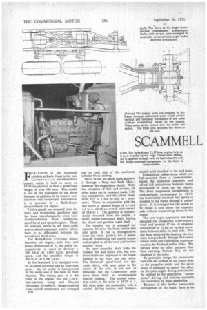
The Rolls-Royce 12.17-litre directinjection oil engine, with bore and stroke dimensions of 5k ins.-and 6 ins. respectively, is rated to develop a 160 b.h.p. at 1,800 r.p.m. governed speed, and the specified torque is 500 lb.-ft. at 1,200 r.p.m.
In the Scammell it is equipped with an all-speed governor and an hours-run meter. An oil cooler is incorporated in the sump and it has twin oil bath cleaners. The timing gear is at the, front of the engine, and the C.A.V. fuel-injection pump and Clayton Dewandre 15-Cubic-ft. flange-mounted water-cooled compressor are arranged
c20 one on each side of the crankcase cylinder-block casting.
Drive to the six-speed main gearbox is through a Borg and Beck 18-in.diameter dry single-plate clutch. With the exception of first and reverse, all other gears are in constant mesh, with dog engagement, and the ratios range from 6.55 'to 1 low to 0.62 to 1 overdrive. These, in conjunction with the two ratios in transfer boxes of 2.5 and 1.3 to 1, afford an overall ratio spread of 19.8 to 1. The gearbox is independently mounted from the engine, a short rubber-cushioned shaft linking the clutch and gearbox input shaft.
The transfer box is arranged for separate drives to the front, centre and rear axles. It has a through-drive from the main gearbox for a power take-off transmitting full engine torqueand coupled to all forward and reverse gearbox ratios.
An open propeller shaft links the transfer box and centre axle, but twopiece shafts are employed in the transmission to the front and rear axles. The Scammell spiral-bevel and epicyclic drive, with spur gears in the centre of the axle, is not new in principle, but the Constructor units have been built to accommodate heavier loading.' The normal reduction ratio in the axles is 10.25 to 1. All three axles are composite, with a central driving section and trumpet
shaped units attached to the end faces. Triangulated radius arms, which are ball-mounted from a cross-member, locate the front-axle assembly and afford full articulation between limits determined by stops on the chassis. The front suspension incorporates a rocking-beam arrangement in which the transversely mounted leaf spring is coupled to the frame through a central pivot. It is arranged for one wheel to be raised a foot above the opposite side without transmitting stress to the frame.
The new bogie suspension has been designed for exceptional cross-country work and permits 17 ins, of diagonal articulation or 12 ins, of vertical movement between axles on each side. This has been achieved by locating the two axles independently through ball-ended torque arms and controlling transverse reaction by Panhard radius links. The springs serve no other purpose than load carrying, because they are not shackled to the axles.
By geometric design, the torque-arm ball ends are 'located on the frame close to the propeller shafts and the pivot point is arranged to cancel the effect on the joint angles during articulation. As implied by the description." torque arms," driving and braking reactions are controlled by these assemblies.
Because of , the double torque-arm arrangement of the bogie, there is no transfer of weight between the axles when driving or braking. The Panhard radius links are similar to the push-pull rod of a steering gear, having two ballend joints attached to the extremities of a threaded tube, one end being fixed to an axle and the other end secured diagonally to the opposite main-frame longitudinal.
The single spring pin at each side of the bogie is enclosed, and the bracket includes an oil reservoir for pin lubrication. At their extremities the springs are attached to two-piece pads shaped to accept a ball-ended joint, a separate component having ,a flat base in sliding contact with a replaceable axle spring perch.
The rubber face of the ball-end member is retained by a heavy cable which encompasses the axle case and permits transverse and longitudinal movement. By this ball-end and . sliding-face arrangement, all torsional and wrapping stresses on the springs are relieved, the relative movement being Controlled in the ball-joint assembly.
The compressor feeds two reservoirs for brake operation and the powerassisted steering. . In addition to the normal cam and double-roller steering box, the drop arm is linked to an external Clayton Dewandre airpressure system. The steering column is divided by a differential, the cage of which operates a reaction valve and delivers compressed air to one or other side of the servo system attached to the drop arm. Working pressure of the air equipment is 85105 lb. per sq. in.
In the main braking system, the levers operating the brake-shoe toggles on the bogie are assisted by air pressure, being linked to central operating cylinders by rods and levers. The front axle units are actuated by direct action controlled by the pedal reaction valve. Connections are provided for operating the brakes on a trailer by _ a two-line • system, arranged so that should the trailer break away, the prime mover would still have air available for braking, but at a reduced pressure of approximately 60 lb. per sq. in. Three air couplings are also provided at the front of the chassis, so that the normal braking system would be available should it be necessary to double head or shunt a trailer.
In addition to the Neates multi-pull hand brake, which operates the bogie brake levers, the Constructor is also equipped with the " hill-holder" device. This comprises a lev'er which is attached to the head of the steering column and is linked to a ,reaction valve supplying air to all brakes.
As a cross-country machine, the new model is equipped with a Scammell vertical-spindle winch for self-recovery or for hauling heavy indivisible loads over difficult territory. The drum accommodates 450 ft. of 23-in.circumference wire rope, which is fed by a mechanical serving gear.
The vehicle can be moved under its own power while winching, and the winch-drive speed can be varied by the ratios in the main gearbox, which is capable of pulling 33,600 lb. from the front or rear.
The Constructor is available with 12.00-20-in. or I2.00-24-in. tyres, with twins at the bogie or single 16.0020-in, covers on single rims at the centre and rear and 12.00-24-in, at the front. Adjustment is made in the axle drives when I2.00-24-in, equipment is employed, the ratio for the centre and rear axles being changed to 11.28 to I.
The maximum tractive effort is 45,000 !b.
In standard form the Constructor is permanently waterproofed to wade through a 2-ft. 6-in. stream, and all components, such as the twin-oil-bath air cleaners, fan and electrical gear, are located well above frame level. The main frame longitudinals are level and parallel from front to centre, but taper to 2 ft. 4 ins, in width in the area adjacent to the second and third axles.
Main members are 12 ins, deep and in. thick and a box stiffener is welded in from the centre to the rear of the chassis. The Constructor, built for use as a tractor, prime mover or load carrier, is available with wheelbases of 15 ft. 9 ins., 18 ft. 3 ins. and 21 ft. 9 ins. and the overall width, governed by the slinging flanges on the front axles is 8 ft. 7 ins.
By tapering the bonnet from front to rear and blending the corner panels. of the cab, the Scamrnell has lost the traditional square build of the conventional cross-country vehicle.