


Injection-pump g By Fuel-consumption Rate
Page 34
If you've noticed an error in this article please click here to report it so we can fix it.
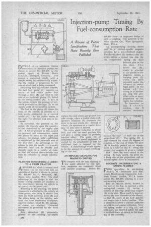
DETAILS of an automatic timing mechanism for injection pumps are shown in patent No. 538,620 by -the patent agents of Robert Bosch G.m.b.H.; Stuttgart, Germany. , The patent is concerned chiefly with a . simple means for automatically adjusting the timing in proportion to the rate at which fuel is being consumed.
Describing first-the complete schema, the fuel feed pumii (9) supplies an excess of fuel which passes first through a filter (6) and then to one side of an hydraulic piston (5) linked to the timing control (3). A leak in the pit ton permits the passage of fuel. -which proceeds via the pipe (2) to the supply ports of the injection system.
The leak in the piston (5) forms the basis of the patent; it consists of a hole partly obstructed by a tapered needle (1). As the piston moves to the right the effective leak area is increased.
In operation, the ,pressure. on the piston (6) depends upon the quantity . of fuel abstracted by the supply pipe (2). A fall of pressure in this, caused by 'increased fuel consumption, causes the piston to move to the right and advance the timing, until equilibrium is established by -the increased area of the leak port. An advantage of the scheme is that the needle (I) is easily .detached, and can be readily and cheaply mi,de in a. -variety of sizes, so that the desired characteristics can soon be obtained by .simple substitution.
PLAN FOR CONVERTING A LORRY TO A FARM TRACTOR
ASCHEME by which a normal road vehicle can be converted into an agricultural tractor is shown in patent No. 538,401 by 0. Bernhard, 187, Maida Vale, London, W.9. The chief advantage of the design is that the heavy towing stresses are confined to the attachment, leaving the vehicle to aet purely as the power unit.
Referring to the drawing, the added framework is attached to the vehicle at three points, one being in vertical line. with the front universal joint (2) and the others being on the existing aide tube, the latter connection incorporating two clamps (4 and 6). The springs, of course; are retained, Universal movement is permitted by the front fixing.
Axle extensions (3) universally jointed to the existing half-shafts replace the road wheels and project into side casings, where a double chain-andsprocket reduction ('7) transmits the drive to the new wheels (I). Instead of wheels, the sprockets of a crawler drive may be used here if desired. The extra speed reduction is about 10-1. and with the usual gearbox this will give a useful range of powerful tractive effort. The pbint (5) of attachment of the towed implement is carried by the attachment so that no additional load is imposed on the vehicle. A disadvantage would appear to be the amount of weight overhanging at the rear: AN IMPULSE COUPLING FOR MAGNETO DRIVES
Tcompete with the easy starting at low speed afforded' by coil ignition, magnetos are commonly fitted with impulse couplings. Patent No.
538,534 shows an imptoved design of such a coupling. The patentee is the Wico Electric Co., West Springfield, Mat's., U.S.A.
An-. accompanying drawing shows part'. of ,a vertical-spindle magneto intended, for a six-cyfindered engine. The driving shaft (2) carries a disc (4) . which drives a second .tree disc (6) . via compression spring (5) fixed between pins on the two discs. T h e driven disc (6),. which is attached to the spindle of the magneto, carries a banging pawl (1) which. can move outwards under the influence of centrifugal force. In the bottom of the casing is a stationary ring (3) provided with as. many projections as the engine has cylinders.
In operation, as disc 4 slowly revolves, disc 6 remains stationary
because the pawl (1)fouls one of the
projections (3). The spring (5) is thus stressed for about 20 degrees of rotation, at the end Of which the pawl (1) is forcibly pushed out of engage-. ment by a lobe on 'disc 4. When this occurs, the magneto is given a violent " kick " from the force stored in the spring. At high speeds, the pawl (1) is flung clear of the projections, and an uninterrupted drive is transmitted.
LOCKNUT INCORPORATING A SPRING WASHER .
rROM slpecialists in nut-locking
devices, 0. , Simitionds and Simmonds Development Corporation, Ltd.. Bush House, London. W.C.2, comes patent No. 538,497. relating to a new nut-securing scheme.
Into an annular recess, formed in the nutat the top, is -inserted a thin spring-steel -washer (2) having a number of inwardly projecting tongues (1) in its bore. These reach to approximately the core diameter-of the thread, so that the entry of the bolt deforms the tongue into a helical outline. This is claimed to create a friction sufficient to hold the nut against vibration. Over the spring washer is a ring (3), and both parts are inserted before the edge, iscaulkecl down as shown in the-drawing of, the assembly.