


FOUR.WHEEL STEERING.
Page 11
Page 12
Page 13
If you've noticed an error in this article please click here to report it so we can fix it.
A Suggestion for the Revival of a Very Early System of Steering Road Vehicles and for its Modernization in Order to Effect Better Load Distribution.
AS we say elsewhere in this issue, despite a rapid improvement generally in road surface conditions,complaints are rife throughout the country of the damage being done by heavy vehicles (and in this category one may include any vehicle which offers tO the road a greater weight than 25 Cwt. or 30 cwt. per wheel).
Unless something be done by designers and manufacturers in an endeavour to secure a mechanical solution of the problem, or .a contribution to that Solution, there is a danger of such pressure being put upon the Ministry of Transport that 'repressive legislation will become unavoidable.
Tite Commercial Motor, some time ago, sought to show how a reconciliation could be effected between the desire upon the part of road engineers for a reduction of axle weights and the need on the part of transport 'organizers for carrying the greatest possible load per unit vehicle. It showed that an increase in the number of road wheels would accomplish this end, and that already some thought had been given to the matter, the most practical method of duplicating a rear axle (that devised by the engin.cering department of the Goodyear Tire and Rubber Co., of Akron, U.S.A.) being described and illustrated in detail.
The possibility of duplicating the front, or steering, axle has also been discussed, and in the issue of The Commercial Motor for Septeinber 12th, the invention of Mr. It. H. Wilkinson, manager of the Tramway Department of the Bradford Corporation, was described. The prOblem in connection with the duplication of the steering axles, wheels and steering connections is the inevitable increase of weight. • In order to render steering easy without an excessive gearing down between the steering wheel and the road wheels, the weight of the vehicle and its load should be carried as to not less than two-thirds on the rear or driving wheels, leaving at the most one third to be shared by the steering wheels. Very
little weight could be saved on the individual parts by reason of duplication, so that, in the result, the weight of the chassis would be increased, and just where it created most difficulty, namely, in front.
But as the distribution of weight over four steering wheels does not, from a designer's point of view, offer so much difficulty as a similar treatment of the load over four driving wheels, we may expect de
signers, when they have come to realize their responsibilities, will take the direction of least resistance and begin by multiplying the number of front wheels, following on with an increase in the number of rear wheels. . It is not easy to say wherethe development would end, but supposing that it went no farther than the duplication of the front and rear axles, it can be seen that even this would reduce the axle weights to about one-half, resulting in a material reduction in road wear and in the cost of road maintenance.
Mr. Wilkinson's invention (which is the subject of a patent) is a step in the right direction of duplicating steering axles, but in our opinion the method is somewhat complicated, and it is difficult to see how the vertical levers mounted on the long horizontal shaft can satisfactorily be connected to the coupling rods of the steering wheels, seeing that one describes a vertical arc while the other describes a horizontal are.
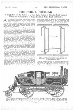
We suggest that the same effect could be achieved by the arrangement shown in Fig. 1, where two ordinary front axles are placed one after the other. They are each provided with the usual coupling bar and arms, the only departure from standard construction
being the arms (A and Al) and the connecting link (B). It will he seen that the arm (A) is slightly shorter than the arm (Al). By this means, the road 'wheels fitted to the forward of the two axles receives
a greater degree of angularity than the rearward wheels, and, so, can turn around any point, and the wheels will track correctly. In the arrangement shown, the steering can be effected either by a foreand-aft rod or by a crossways rod, the latter being indicated in the sketch in order to follow out Mr. Wilkinson's intention of applying four wheels for the steering of rail-less trolley-buses.
It is in the case of the trolley-bus that this question of multiplying the number of steering wheels becomes urgent—not from the road point of view, but from that of weight distribution. Consideration for the road, it will thus be seen, still occupies the secondary place in the estimation of the vehicle designer! In the trolley-bus or rail-less car, the tendency is for the preponderance of the total weightl to go forward. The controller, brake gear, trolley pole and standard, and the driver are well to the front, whilst the motors are mounted about central in the
chassis. Then the absence of an engine in front brings the load of passengers more over th4 steering wheels. Thus, for some time, it has been./decided that the build of the whole vehicle must resemble that of a tramcar rather than that of the motor bus.
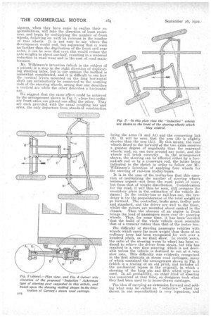
The difficulty of steering passenger vehicles with wheels which carry far more weight than those of an ordinary lorry has been recognized for well over a hundred years, as we shall show. In recent years, the ratio of the steering worm to wheel has been reduced to relieve the driver from strain, but this has resulted in a very slow steering, which is not desirable unless the vehicle is destined to run at a very slow rate. This difficulty was evidently recognized in the first attempts at steam road carriages, many of which contained the arrangement shown in Fig. 2 (which is a tracing of an old print, and includes all the mechanical lapses in the original), in which a steering of the king in and fifth wheel type was used. In all probability, no other kind of steering was conceived at that time, so designers took what they had been used to in horse-drawn carriages.
. The idea Cd carrying an extension forward and adding what may be called an " inductive " wheel (as shown in our reproduction) is very ingenious, and
shows shows that, even at that early time, many active brains were at work. This " inductive " wheel could be steered with the minimum of effort7 as it only induced the other wheels to follow its direction. It is curious that this principle has not been recognized as something that might be developed to suit modern requirements.
Recognizing the need for better steering arrangements on trolley cars, we have followed up the line of thought opened up by a study of this old print, and have produced what we have christened the "Inductive Ackerman" type. This is a wedding of the modern and the ancient, and in Figs. 3, 4 and 5 we set it out as we imagine it.
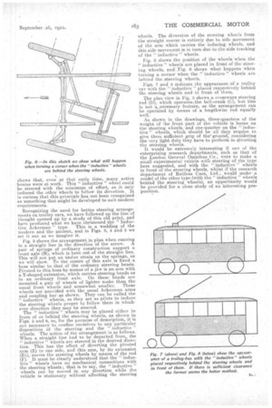
Fig. 3 shows the arrangement, in plan when running in a straight line in the direction of the arrow. A pair of springs of ordinary construction support a front axle (H), which is bent out of the straight line. This will not put an undue strain on the springs, as we will show. To the centre of this axle is fixed a boss similar to that of the ordinary steering heads. Pivoted to this boss by means of a jaw is an arm with a T-shaped extension, which carries steering heads as in an ordinary front axle. On these heads are mounted a pair of wheels of lighter make than the usual front wheels and somewhat smaller. These wheels are provided with the usual Ackerman arms and coupling bar as shown. They can be called the " inductive " wheels, as they act as pilots to induce the steering wheels proper to follow them in whichever direction they may be steered. The inductive" wheels may be placed either in front of Or behind the steering wheels, as shown in Figs. 5 and 6, so, for the purpose of description, it Is not necessary to confine ourselves to any particular disposition of the steering and the inductive " wheels. The action of the arrangement is as follows. When a straight line had to be departed from the " inductive" wheels are steered in the desired direction. This has the effect of diverting the pivoted arm (E) to one side, and this arm, by its extension (El), moves the steering wheels by means of the rod (F). It must be clearly understood that the " inductive " wheels have no mechanical connections with the steering wheels ; that is to say, the " inductive " wheels can be moved in, any direction while the vehicle is stationary without affecting the steering wheels. The diversion of the steering wheels from the straight course is entirely due to side movement of the arm which carries the inducing wheels, and this side movement is in turn due to the side tracking of the "inductive " wheels.
Fig. 5 shows the position of the wheels when the "inductive " wheels are placed in front. of the steering wheels, and Fig. 6 shows What happens when turning a corner when the " inductive." wheels are behind the ,steering wheels.
Figs. 7 and 8 indicate the appearance of a trolley car with the "inductive " placed respectively behind the steering wheels and in front of theme The plan view in Fig. 3 shows a crossways steering rod (D), which operates; the bell-crank (CI), but this is not a,..neeessary feature, as the arrangement can be operated by means of a lengthwise rod equally well.
As shown in the drawings, three-quarters of the weight of the front part of the vehicle is borne on the steering wheels, and one-quarter on the " inductive " wheels which 'should be all they require to give them sufficient grip of the' ground, considering the very light duty they have to perform in diverting the steering wheels.
It would be extremely interesting if one of the enterprising research departments, such as that of the London General Omnibus Co., were to make a small experimental vehicle with steering of the type here suggested, and with the "inductive " wheels in front of the steering wheels, whilst if the research department of Railless Cars, Ltd., would make: a model of the other type (with the " inductive " wheels behind the steering wheels), an opportunity would be provided for a close study of an interesting proposition.