


A Self-adjusting Suspension System
Page 66
If you've noticed an error in this article please click here to report it so we can fix it.
PATENT NO. 756,026 shows a suspension system in which the spring resistance automatically increases with an increase of load, thus keeping the height of the vehicle constant. The patent comes from Motor Research Corporation, 825 Fisher Building, Detroit 2, Michigan, U.S.A.
The drawing shows the principle applied to the suspension of a heavy vehicle. The wheels are carried on swinging linkages (1) and the main resilient member is a pair of torsion rods (2), running longitudinally. These are designed to carry only the unladen weight of the vehicle.
In parallel with each of the torsion rods is a second one (3) to deal with the added load. This is anchored in a worm wheel (4), and the corresponding worms are mounted on two common cross-shafts each rotatable by an electric motor (5).
A height-sensitive switch controls the motors, running them one way or the other to modify the torque applied to the auxiliary rods. The effect of an increase in load is to wind up the torsion rods by an amount sufficient to restore the vehicle to its normal height. The switch has an action. delay to prevent transient adjustments.
The arrangement permits a very soft main springing to be used, the one mentioned having a rate of only 30 lb. per in. of wheel-lift.
POWER STEERING FOR HEAVY VEHICLES
Q MALL structural dimensions and LJ rugged construction are the virtues claimed for a servo-power steering system shown in patent No. 755,168 (E. and H. Teves, Rebstockerstrasse 41-53, Frankfurt/Main, Germany). The scheme is also said to give the driver a sense of the effort exerted by the power.
The steering rodwork (1) is moved by a lever (2) which is pivoted at 3 on an upward extension of the drop arm. At the mid-point the lever moves, via a pin (4), a slide-valve sleeve (5). The slide-valve controls a double-acting hydraulic cylinder (6) which applies an amplified force to the rodwork.
The drop arm (7) surrounds pin 4 with a slight clearance and works the central bobbin (8) Of the slide-valve, thus imparting a self-lapping follow-up action at all positions.
TYRE WITH REPLACEABLE TREAD
EFFORTS have been made in the past to provide a renewable tread for a tyre, but hitherto they have not been successful, the chief defect being that the high tangential loads cause the tread to shift with respect to the tyre in a circumferential direction. This creates, in turn, friction, heat and wear.
B12 The problem is now claimed to have been solved by a new design shown in patent No. 755,990 (Pirelli Societa Per Azioni, Milan, Italy). In the scheme suggested, no attempt is made to key the tread, the mating surfaces being perfectly smooth.
The drive is • transmitted purely by s friction between the tread (1) and the tyre, and the friction is set up by inflation pressure. For this to be effective, the tread portion must be inextensible.
This is done by incorporating wires, threads or other non-stretching strands in a band (2) across the tread. Under inflation, the tread is held as firmly to the tyres as the tyre is to the rim, and slip is said to be impossible. To remove the tread it is necessary only to deflate the tyre.
COATED PISTONS AND RINGS
A COMPARATIVELY recent new plastics material, polytetrafluoroethylene—PTFE --is now coming into wide use for a variety of purposes. This material has a very low co-efficient of friction, said to be equal to that of ice, and is often used because of this property. A novel scheme for coating pistons and piston-rings with it comes in patent No. 754,870, (General Motors Corp., Detroit, Michigan, U.S.A.).
The piston is coated on its crown for the reason that ATFE is also a poor heat-conductor, and the layer /irevents heat descending into the piston. A layer an the skirt is provided to minimize friction.
The thickness of the layers is between '0.001 in. and 0.005 in. The rubbing face of the piston rings is also covered with a layer. The patent gives full details of the process used in depositing the coating. It also mentions that tests
equivalent to 10,000 miles of road running have shown the coating to be intact at the end.
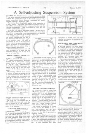
INSTRUMENT FOR INDICATING AVERAGE SPEED
QN long journeys it is often useful for the driver to know whether he is ahead of, or behind, schedule, and this usually involves some arithmetic. An instrument which given a continuous .account of the journey forms the subject of patent No. 756,036 (C. Phillips, 127 Coleherne Court, Old Brompton Road, London, S.W.5.).
The instrument comprises a fixed dial (1) which can be calibrated in any desired number of miles; the one shown reads up to 60. Around this moves a pointer (2) driven by the transmission and recording the distance travelled. A second pointer (3) is moved steadily by clockwork at a selected speed, say 30 calibrated m.p.h.; this can be pre-set by a drum (4).
If the average speed of the vehicle were exactly that chosen, then the two pointers would move together. In practice, however, the distance pointer would be either ahead of or behind the time pointer, thus giving the driver an instant indication of his position.
In case a wide angle between the two pointers should leave a doubt as to whether the speed is leading or lagging, a small window (5) exposes a dial giving the information. In addition, a diminishing mileometer (6) can be pre-set to the total projected journey and shows at any moment the number of miles to go.