


HINTS ON MAINTENANCE.
Page 64
If you've noticed an error in this article please click here to report it so we can fix it.
A Crossley Brake Improvement. Reassembling a Timken Axle. How to Trace Weak Valve Springs.
Improving the Rear-wheel Brakes on an Old.type Crossley In the older types of R.A.F. Crossley trouble is sometimes experienced with the rear-wheel brakes, the adjustment being very fine, due to the small amount of travel of the brake arms, and constant adjustment is necessary to keep the brakes up to the mark. The method of compensating also requires special attention, as the whole of the pull appears to come to the side nearer to the hand-brake lever.
One of our readers who does a great many repairs on this class of vehicle has had a number of such cases to deal with. In one case in which a Crossley carrying a coach body broke the rear-axle shaft, thus putting the foot brake out of action, the hand lever, although properly adjusted at the beginning of the run, proved almost ineffective after a long day's work in hilly country. It was, therefore, decided to alter the brake layout.
First, all the brake rods were taken off, the two adjustable ones at the rear being made of exactly the same length, the two other rods being similarly treated. The short rod carrying the hand adjusting screw was slackened off to its fullest extent, and the compensating link scrapped. A piece of flat mild steel, 2 ins, wide and in. thick, was obtained, and four pieces were cut off from this, two 2 ins, wide and 2i ins, long and two, with prongs, having the dimensions given in the illustration. The distance between the prongs cannot be given exactly, as this varies a little on each car, but these pieces must be made a tight fit up each side of the brake toggle to prevent rock when in position and when the brake is applied. These pronged pieces should be held to the existing toggles by well-fitted bolts. The general layout of the arrangement can be seen from the upper diagram. It makes the brakes positive in both the " on " and " off " positions, giveh more leverage to the brake arms and further travel, thus allowing a greater margin between the " on " and " off " positions.
To adjust the brakes, when fitted up, jack up both wheels and set the brake arms on each side to the same point. This is easily effected, as they have serrated faces for adjustment. Then put on the brake, and if one set of shoes bites before the other, set up one tooth on the serrations. If this be too much, adjust by means of the right and left-hand-threaded nut on the rod.
After wear has taken place, adjustment can be made for a considerable time by means of the hand-adjusting nut at the bottom of the brake lever. It will be found that the lever is slightly harder to pull on, but the improvement in the braking is certainly worth while. The total first cost is only a few shillings, and after 18 months' use this form of brake layout is working splendidly on a Dumber of these vehicles working in hilly districts.
Reassembling the Timken Rear Axle.
One of our readers made a serious mistake when reassembling the Timken rear axle of a 30-cwt. MaxwelL Each shaft of this axle is spilled at one end and the
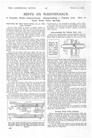
shafts are retained by taper roller bearings mounted at the outer ends. In the centre of the differential casing and between the inner ends of the two axle shafts is a white-metal washer about twice the size of a penny both in diameter and thickness, so that when the vehicle is cornering and one axle shaft is revolving at a greater speed than the other, the washer, or disc, as It would perhaps be better to call it, forms a kind of thrust !Searing between the shafts.
The disc is inserted when assembling the differential and is free to move to either side in recesses cut' into the internally splined sleeves forming part of the bevel wheels. When both axle shafts are removed, this disc can fall over until it lies flat. If one axle shaft be then inserted and the adjusting sleeve on its roller race tightened until the adjustment is approximately correct, the disc may be forced past the recess opposite to that shaft, as shown in our diagram, and it cannot then return to its correct vertical position unless the washer which is holding it be released.
The result is that when the second axle shaft is replaced it cannot be inserted to the correct depth in its sleeve. In fact, the ends of the shafts may be held 2 ins, apart, but after driving in this conditlott for a few miles the thrust causes the disc to bend and, finally, to return to an almost vertical position, thus leaving the axle shafts with nearly 2 ins, of play, which, unless noticed quickly, results in the complete destruction of the taper roller bearings and may, as happened in the case in point (when the driver, finding the vehicle would not pull on top gear, drove home on second), also result in destruction of the axle shafts.
It is, therefore, advisable for any mechanic working on an axle a this type to keep a watchful eye on this small but important disc.
Tracing Weak Valve Springs.
Weak valve springs can be easily located while the engine is working by inserting a screwdriver between a pair of coils and giving the tool a slight twist to increase the spring pressure. Should the engine immediately pick up speed, the spring is normally too weak. When making this test it is advisable to let the engine run fairly quickly.
It will be found that exhaust-valve springs give the most trouble; these lose their strength by the heat to which they are subjected.