


Patents Completed.
Page 24
If you've noticed an error in this article please click here to report it so we can fix it.
Sparking Plug Construction. Laminated Spring Improvements. A Heavy,
fuel Engine. Equable Springing Action.
Copies of complete specifications of the patents published on this page can be obtained from the Sales Branch, Patent Office, Holborn, W.C., al the cost of sixpence for each specification.
K. E. L. Gin:slims, No. 101,197, dated 8th "May, 1916.—In order to make a sparking plug electrode joint capable of resisting the higher pressures and temperatures now in use, especially in aeroplane engines, the inventor clamps a portion of the mica washers between two metal surfaces. The invention is applied to several types of plug, one of which is illustrated.
In this example the electrode is made of steel with nickel point. On the electrode a large collar is formed which projscts into the mica washers and is insulated at its circumference by mica wrapping. The mica washers between this collar and the internal retaining nut are pressed together to form a strong gastight joint—the pressure being applied by the hexagon nut at the outer end of the plug. The invention includes a wire deaning,tool for certain types of plug.
BROWN BATLEY'S STEEL WORKS, LTD., and T. H. SANDERS, No. 16,450, dated 22nd November, 1915.—This invention consists in forming the sides of leaf springs, at mid-length where they are held by the buckle, with recesses to engage the ends and sides of the buckle for the purpose of taking the driving stress. The edges of the springs may be recessed to receive the sides of the buckle or swaged to provide projections, as in the example of the invention shown in the drawing. In another form twin projections are swaged out to receive the bolts where aclamp is used instead of a buckle. The recessing may be appliedto some or all of the leaves.
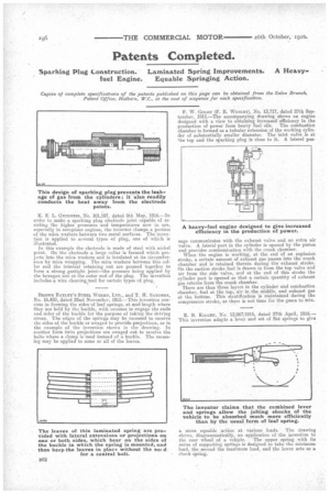
F. W. GOLBY (F. R. WRIGHT), No. 13,717, dated 27th September, 1915.—The accompanying drawing shows an engine designed with a view to obtaining increased efficiency in .the prpduction of power from heavy fuel oils. The combustion chamber is formed as a tubular extension of the working cylinder of substantially smaller diameter. The inlet valve is at 'Jae top and the sparking plug is close to it. A lateral pas sage communicates with the exhaust valve and an extra air valve. A lateral port in the cylinder is opened by the piston and provides communication with the crank chamber. When the engine is working, at the end of an explosion stroke, a certain amount of exhaust gas passes into the crank chamber and is retained therein during the exhaust stroke. On the suction stroke fuel is drawn in from the top valve and air from the side valve, and at the end of this stroke the cylinder port is opened so that a certain quantity of exhaust gas returns from the crank chamber. There are thus three layers in the cylinder and combustion chamber, fuel at the top, air in the middle, and exhaust gas at the bottom. This stratification is maintained during the compression stroke, as there is not time for the gases to mix.
a more equable action at various loads. The drawing shows, diagrammatically, an application of the invention to
the rear wheel of a vehtcle. The upper spring with its series of supporting springs is designed to take the minimum load, the second the maximum load, and the lower acts as a check spring.