


Patents Completed.
Page 22
If you've noticed an error in this article please click here to report it so we can fix it.
Complete specifications of the following patents will be sent to any address in the United Kingdom eo upon receipt of eightpence per copy at the Sale Branch, Patent Office, Holborn, W.C.
MACHINE FOR ROAD MAKING.— Coutant and Salmson.—No. 2,624, dated 1st February, 1911.—One of the disadvantages of ordinary road rollers is that the material is forced in a longitudinal direction by the action of rolling and in a lateral direction by the sinking
of the roller into the material. As a result of this continuous movement the edges of the broken stone or gravel are crushed so that the binding action is spoiled. According to the present invention the consolidation of the road is achieved by the use of a series of beaters which are allowed to fall on the rnad surface and have a forward smoothing actioa as well. These beaters are at
on the front of the machine and are lifted by means of cables attached to hooks carried in suitable guides. These hooks are engaged at intervals by pins s on a constantly-rotating wheel. The beaters are lifted to a height adjusted according to the surface or nature of the road being worked and are automatically released in turn, when they fall and con solidate the surface material. Before being lifted, the travel of the locomotive has carried them forward, thus giving them a slight smoothing action. The. varions details of the mechanism are fully described and illustrated.
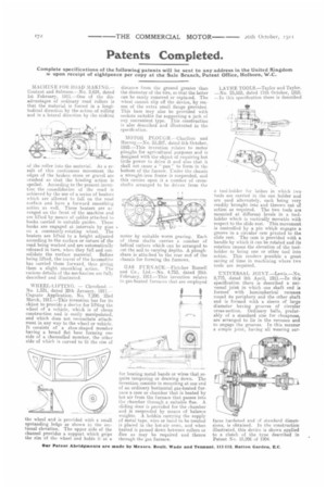
WHEEL-LIFTING. — Cleveland. — No. 1,531, dated 20th January, 1911.-Cognate Application, No. 7,290. 23rd March, 1911.—This invention has for its objeot to provide a device for lifting the wheel of a vehicle, which is of cheap construction and is easily manipulated, and which does not necessitate attachment in any way to the wheel or vehicle. It consists of a shoe-shaped member having a broad flat base forming one side of a channelled member, the other side of which is curved to fit the rim of the wheel and is provided with a small upstanding ledge as shown in the sectional elevation. The upper side of the channel provides a support which grips the rim of the wheel and holds it at a distance front the ground greater than the diameter of the tire, so that the latter can be easily removed or replaced. The wheel cannot slip off the device, by reason of the extra small flange provided. This base may also be provided with sockets suitable for supporting a jack of any convenient type. This construction is also described and illustrated in the specification.
MOTOR PLOT:CH.—Charlton and Harvey.—No. 23,287, dated 8th October, 1910.—This invention relates to motor ploughs for agricultural purposes and is designed with the object of requiring but little power to drive it and also that it shall not cause a " pan " to form in the bottom of the furrow. Ender the chassis a wrought-iron frame is suspended, and this carries upon it a number of crossshafts arranged to be driven from the motor by suitable worm gearing. Each of these shafts carries a number of helical cutters which can be arranged to cut the soil to varying depths. A ploughshare is attached to the rear end of the chassis for forming the furrows.
GAS FURNACE.—Fletcher Russell and Co., Ltd.—No. 4,753, dated 25th February, 1911.—This invention relates to gas-heated furnaces that are employed for heating metal bands or wires that require tempering or drawing down. The invention consists in mounting at one end of an ordinary horizontal gas-heated furnace a case or chamber that is heated by hot air from the furnace that passes into the chamber through a suitable flue. A sliding door is provided for the chamber and is suspended by means of balance weights. A bobbin carrying the supply of metal tape, wire or band to be treated is placed in the hot-air oven, and when heated is passed down between rollers or dies as may be required and thence through the gas furnace. LATHE TOOLS.—Taylor and Taylor. —No. 23,503, dated 11th October, 1910. —In this specification there is described
a tool-holder for lathes in which two tools are carried in the one holder and are used alternately, each being very readily brought into and thrown out of action as required. The two tools are mounted at different levels in a toolholder which is vertically movable with respect to the slide rest. This movement is controlled by a pin which engages a groove in a circular cam pivoted to the slide rest.. The cam is provided with a handle by which it can be rotated and its rotation causes the elevation of the toolholder to bring one or other tool into action. This renders possible a great saving of time in machining where two tools are required.
UNIVERSAL JOI N T. —Lewis. —No. 8,775, dated 8th April, 1911.—In this specification there is described a universal joint in which one shaft end is formed with hemispherical recesses round its periphery and the other shaft end is formed with a sleeve of large diameter having grooves of circular cross-section. Ordinary balls, preferably of a standard size for cheapness, are arranged to lie in the recesses and to engage the grooves. In this manner a simple joint, having all wearing sur
faces hardened and of standard dimensions, is obtained. In the construction illustrated, this device is shown applied to a clutch of the type described in Patent No. 15,206 of 1904.