


An Electrically Powered Steering Servo
Page 54
If you've noticed an error in this article please click here to report it so we can fix it.
A Resume of Recently Published Patent Specifications
A STEERING system for heavy road vehicles is shown in patent No. 603,281, by G: Olah, and the Precision Developments Co., Ltd., 3, St. James's Square, London. S.W.I. . The scheme employs a servo motor controlled by the steering -wheel, the extra power being derived from a source of electricity, possibly the batteries of the vehicle.
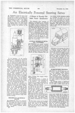
In the drawing, I is the steering column which terminates in a flange (2). The latter is connected by pins to a geat (3) fixed to the output shaft (4). The pin connection is given a little lost motion, but is capable of allowing the steering to be worked entirely by hand should the electric power fail.
The power is applied in the following manner: the electric motor (5) drives, via reduction gears, a pinion (6) which is geared to the output shaft. The switching arrangements are ingenious; they comprise a pair of insulated pinions (7) driven by a single insulated gear (8) which is rotated by the steering column. The two pinions have a slight backlash so that rotation in one direction connects one of them electrically with the driving gear, at the same time disconnecting the other.
When the column is turned in the opposite direction, the other pinion is connected, so that they act as a selector switch to the field windings of the motor, which is provided with forward and reverse fields. A. solenoid (9) throws the motor out of mesh 'when the power fails, so as to ease the driver's work. Another feature of the scheme is that the servo motor is automatically braked by spring pressure except when actually working.
PROGRESS IN ALUMINIUM ALLOYS
ALUMINIUM alloys are constantly being improved, and a new formula for one forms the subject of patent No. 604,813. The patentee is T. Bradbury 57, Windley Crescent, Darley Abbey, Derby.
A36 The proposed alloy contains, in addition to aluminium, the following percentages of other elements: Copper 1.5, nickel 3, zinc 6.1, magnesium 2.2. Manganese 1.8, silicon 0.2 and iron 2.2. To bring out the full properties of the alloy, it is first worked, then solution heat-treated by quenching from 520 degrees C., and finally aged for seven hours at a temperature of 135 degrees C. The resulting Brinell hardness figure was found to be 218, whilst the tensile strength was 44 tons per sq.. in. The patent also covers the addition of other elements, 16 in number, up to a total.
figure of 1.5 per cent. .
UNUSUAL METHOD OF SECURING A FLYWHEEL
FLYWHEELS are usually attached to the crankshaft close to a bearing which is provided with an oil seal, and when this has to be renewed, extensive dismantling is called for. To avoid this is the object of a new method of attaching the flywheel shown in patent No. 603,955, by Henry Meadows, Ltd., and
others, Fallings Park Engine Works, Wolverhampton.
The drawing shows a section in which 1 is the end of the crankshaft and 2 the flywheel. The crankshaft is formed with an integral enlargement (3) which is radially drilled with, say, six holes (4). Each hole contains a cylindrical nut (5) to receive the end of the bolt (6) for clamping the flywheel. The nuts are split, and the thread on one half is slightly displaced with respect to the other, so as to give a gripping effect when the bolts are screwed home. The group of nuts is held in place by a spring-ring, which also ensures alignment of the holes. The bolt heads are also drilled, presumably for a locking wire.
By this means, access can be gained to the oil-seal by removing only the flywheel; also, there is an absence of stresses on the bolts due to misalignment, because the nuts, in effect, form a universal joint. VAN BODY WITH SLIDING SIDES
CIA CLOSED van which can provide all the accessibility of an open body is shown in patent No. 603,661, by A. .Vines, and the Fairey Aviation Co., Ltd., North Hyde Road, Hayes, Middlesex. The sides of the body are made to slide after the fashion of a roll-top desk.
.Referring to the drawing, the roof is a cantilever structure, supported by two uprights inside the doors, and putting the windscreen region in tension. The door is a sliding member, and can be moved rearwards into a position in which it overlaps the body. The body sides are built up from slats (2) which are slidable in two sets of runners, one inside the other, so that one side of the body can be slid completely round to the other, leaving half the body open. Removable sections on the runners permit the sides to be completely detached if desired. This type of body v;ould seem to be eminently practicable.
RUBBER-BUSHED SHACKLES
'ATENT No. 603,297 bears two wellknown names, Leyland Motors, Lid., and Metalastic, Ltd., Evington Valley Road, Leicester, and refers to the application of bonded-rubber bushes to spring shackles. The scheme deals with a simple means for adjusting the initial tension in the joint when assembled.
The drawing shows a shackle-pin assembly which consists of three parts, the pin itself, a rubber sleeve and an outer metal sheath, all of which are bonded into a unit; this is intended to be pressed into the eye on the end of the spring. To allow of adjustment of stress, the pin is provided with serrated ends (1) which engage with anchor plates attached to the shackles, so that they can he locked in any desired condition of rest or pre-loading. Tha anchor plate can be fitted in any position on the serrations, and is further provided with a fine adjustment