Little and Often in Chassis Lubrication
Page 9

If you've noticed an error in this article please click here to report it so we can fix it.
ONE of the most interesting of the new accessories that were introduced at the recent Commercial Motor Show. and one that represents a valuable progressive step, is the R.P. chassis lubricator, a product of Clayton Dewandre Co., Ltd., Titanic Works, Lincoln. This ingenious device was shown mounted on a Daimler chassis and in cut-away form,
The object of the chassis lubricator is to reduce maintenance. It performs, an operation, normally included in servicing, automatically and more efficiently than by the conventional method. Each time the driver applies his brake, the device delivers a drop of oil to one of a number of chassis points, every bearing requiring lubricant being thus supplied in rotation. Chassis lubrication is thus looked after with far greater regularity and frequency than would be the case with the best maintenance system. Moreover, there is no possibility of dirt, grit or water entering a bearing or obstructing an oil passage leading to it.
No more than a small quantity of oil is discharged at a time, and the amount can be separately controlled for each point. There is no question, for example, of a worn shackle taking a lot at the expense of a bearing that is on the tight side. In addition, there is a master adjustment so that the amounts delivered to all points can be increased or diminished simultaneously when an alteration is made to the conditions under .which a vehicle operates. Oil is, therefore, consumed at a low rate.
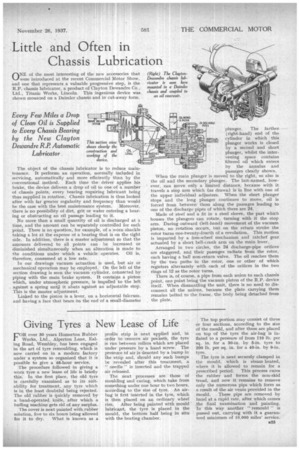
In our drawings vacuum actuation is used, but air or mechanical operation may be employed. On the left of the section drawing is seen the vacuum cylinder, connected by piping with the main brake system. It contains a piston which, under atmospheric pressure, is impelled to the left against a spring until it abuts against an adjustable stop. This is the master adjustment.
Linked to the piston is a lever, on a horizontal fulcrum, and having a face that bears on the end of a small-diameter
plunger. The farther-(right-hand) end of the cylinder in which this plunger works is closed by a second and short plunger, whilst the intervening space contains filtered oil which enters by the annulus and passages clearly shown.
When the main plunger is moved to the right, so also is the oil and the secondary plunger. The last-named, however, can move only a limited distance, because with it travels a stop arm which (as drawn) is in line with one of the upper individual adjusters. When the short plunger stops and the long plunger continues to move, oil is forced from between them along the passages leading to one of the discharge pipes of which there are 24.
Made of steel and a fit in a steel sleeve, the part which houses the plungers can rotate, turning with it the stop arm. Dining outward (left-hand) movement of the vacuum piston, no rotation occurs, hut on the return stroke the rotor turns one-twenty-fourth of a revolution. This motion is imparted by a free-wheel mechanism and ratchet gear actuated by a short bell-crank arm on the main lever. Arranged in two circles, the 24 discharge-pipe orifices are staggered, and their passages radiate from the rotor, each having a ball non-return valve. The oil reaches them by the two paths in the rotor, one or other of which registers alternately with. each of the orifices in the two rings of 12 as the rotor turns. There is, of course, a pipe from each union to each chassis point, one point being the vacuum piston of the R.P. device itself. When dismantling the unit, there is no need to disconnect all the unions, because the plate carrying them remains bolted to the frame, the body being detached from the plate.


