


Starting-handle Ignition Retarder
Page 30
If you've noticed an error in this article please click here to report it so we can fix it.
A Résumé of Recently Pub.. lished Patent Specifications
solutions, such as sulphate of copper, iron or manganese. Vertical guards suspended from--the frame are used to localize tyre flames, and the whole scheme is directed not only towards prevention but also towards insulation of the interior from damage by even local fires.
Novel Principle for Injection Pumps.
"THE modern injection pump is 1 probably the finest example of workmanship possible in commercial engineering, a fact which is naturally
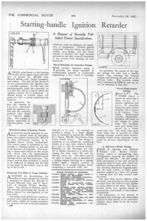
A SMALL attachment to the starting
handle of an engine forms the subject of patent No. 473,474 from Karrier Motors, Ltd., Stoke, Coventry, and others. The aim of the device is to set automatically the ignition into a retarded position. To this end, the starting-handle shaft has mounted on it a free disc (2) to a lug of which the ignition control (1) is connected. A double facing of friction fabric (3) grips the disc, a spring supplying the pressure.
In operation, the first. few degrees of handle movement pulls the ignition control into the retarded_ position, after which t h e friction clutch slips. The scheme is equally applicable to injection-pump control.
Rotational-spray Injection Nozzle.
AN injectionnozzle intended to produce a conical sheet of fuel-spray forms the subject of patent No. 473,174 by that well-known concern, S. A. Adolphe Saurer, Arbon, Switzerland. The conical spray is produced by imparting a whirling motion to the fuel at the moment of injection. The drawing, a large-scale section of the nozzle end, shows how the spring-loaded needle is cut with a multi-helical thread through which the fuel must pass. The rotary motion thus produced is stated to be sufficient to spread out the fuel to the angle of the hollow cone at the tip of the nozzle.
Reducing Fire Risk in Large Vehicles.
.A SCHEME for fire-proofing the .tA bodies of large commercial vehicles is described in patent No 473,154 by Oswald Tillotson, Ltd., and F. Shaw, both of Summit Works, Burnley, Lancs. The scheme is. directed especially towards preventing the spread of flames 'caused by auto-ignition of the rear tyres.
The metal body panels are coated or sprayed with asbestos fibres, on one or both sides, whilst all wooden members are treated with one of the fire-resistant B46 reflected in its cost. An attempt to produce a pump of a much simpler type is disclosed in patent Na. 473,038 by J. Boyle, 193-197, Bree Street, Cape Town, South Africa. The design is ingenious in its simplicity, consisting merely of a bent tube which is flexed by a cam to vary the internal volume. Referring to the drawings, the tube (3) is rigidly attached to a block containing the inlet valve (2) and the delivery valve (1). The lower end of the tube is closed, and is attached to a sliding tappet moving in a springloaded guide. Output control is obtained by a stroke-varying device comprising a movable roller (4). In operation, the ascent of the tappet springs the tube into a smaller radius, thus reducing the internal volume and ejecting the fuel out of the delivery valve. The inventor states that a pressure of 2,200 lb. per sq. in. can be obtained in this' way.
Novel Body-bearer Design.
DATENT No. 1 473,635 shows a means for attaching a' lorry body to a chassis, lightness and e a-s e of assembly being the chief virtues claimed. The inventor is R. Clayton, Three Elms, Rothamsted Avenue, Harpenden. Brackets (2) fixed to the frame in pairs form the uprights, each pair being confleeted by a transverse tube (I). The body rests upon these tubes and is secured by bolts passing through vertical holes therein, packing bushes, being internally interposed to prevent squeezing-in of the tube.
A Self-servo Brake Design.
FROM R. Mehatly and Richard Klinger, Ltd., Rtudey Corner, Sidcup, comes a self-applying shoe
arrangement, forming the subject of patent No. 473,110. In this design early movement of the cam serves to bring the shoes to bear, after which the self-servo action assists the main force.
The drawing illustrates diagrammatically the basic action, in which pedal pressure applied to a lever (1) presses a floating shoe (3) into contact with the drum.
The shoo then moves slightly with the drum, and in doing so abuts against a second lever (2) which in turn applies an extra effort to the shoe. The specification shows two specific forms of construction and details of the relative proportions. An adaptation of the scheme is described and although the mechanism
appears at first glance to be somewhat complex there seetn to be no seriou, difficulties,