


A Promising Automatic Variable Gear
Page 58
Page 59
If you've noticed an error in this article please click here to report it so we can fix it.
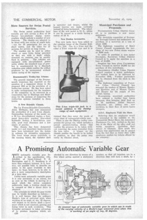
rilHE automatic variable gear 'de
scribed in the specification (No. 318,938) of Lieut.-Colonel T. B. Barrington and C. P. Sandberg is of more than ordinary interest. It is, however, not possible fully to describe its action in the space available in this issue ; we hope, however, to be able to give a more comprehensive description sit a later date.
Unlike most automatic variable gears it is only automatic to an extent, for so soon as the vehicle is moving at a speed which the driver considers sufficiently high, a friction clutch. can be engaged so that a direct drive is obtained.
The principle on which the gear works may be briefly described as follows:— It is well known that the ordinary Hooke's type of universal joint, when working at an angle of, say, 45 degrees, will impart to its driven shaft a movement which is not constant, gaining and losing twice in each revolution. This irregular movement is taken advantage of to produce impulses which. are C20 checked in one direction by means of a free wheel acting against a stationary
member, so that all impulses are in a direction that will turn a shaft, by t, step-by-step motion, always in the direction which drives the vehicle forward. A second free wheel is provided which allows the vehicle to continue in a forward direction in the intervals between the impulses.
The frequency and magnitude of the impulses are governed by the speed at which the engine runs and the total resistance of the vehicle ; these impulses gather amplitude as the resistance of the car decreases until in the judgment of the driver the friction clutch (not shown) can be engaged. A brief description of the drawing is as follows :—A is the engine shaft, B the flywheel which carries a boss in which the shaft (C) can revolve freely. Attached to C is one member of a Hook's joint of the four-trunnion-andring type, the other member being attached to the shaft (D) which carries the inner member of the free wheel (VI). A second llooke's joint of larger diameter surrounds the one previously mentioned and is attached to the bell-shaped member. (I) and the hollow shaft (Hi). This member has _considerable weight, and consequently resists rapid oscillatory movement, thus imparting an oscillatory movement in the shaft (D), the backward movements of which are checked by the free wheel (Vi-), but permits the second fret wheel (V2) to impart a forward movement through the shaft (E) to drive the ear forward, the free wheels being set to operate in opposite directions.
The sectional view on the right is through a line cutting the centre of the two Hooke's joints and shows one inside the other.