


Patents Completed.
Page 20
If you've noticed an error in this article please click here to report it so we can fix it.
CAR.I3VRETTER — 13urstall. — No. 23,546, dated 25th October, 1907.This invention relates to carburetters of the type in which wire gauze is employed as
a medium for the vaporisation of the fuel. The carburetter consists of the casing (131, provided with inlets and outlets (A, D) and a removable cover (C). Within the casing (B) is arranged wire gauze (E) having a honeycomb formation. Such formation produces a continuity of surface for the vaporisation of the fuel either before or after it is mixed with air. The casing (B (is provided with a jacket (F) through which the exhaust gases are caused to pass.
NON-SKID DEVICE. — Middleton.— No. 23,125, dated 19th October, 1907.— This device consists of a cylinder (t) pivoted at d to a ring (al which runs on ball bearings on the axle box (b). Within the cylinder (c) is arranged a plunger r) to which is secured a bar as shown in the illustration. This bar supports a number of chains (g) which are linked together and which hang down in close proximity to the tire of the wheel. A spiral spring is arranged between the plunger (e) and the cylinder. It will be seen that when skidding commences the wheel passes on to the chains (g) and draws them down under it, thus preventing further skidding When the wheel has passed over the chains the spiral spring restores them to their normal position. A wire (i) is provided to prevent the device froth turning on the axle box, and also this may be used for the withdrawal of the device when it is not required for use.
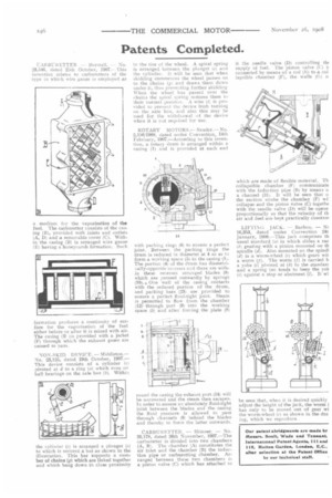
ROTARY MOTORS.— Neader.— No. 2,150/1908, dated under Convention, 14th February, 1907.—According to this invention, a rotary drum is arranged within a casing (1) and is provided at each end with packing rings 16) to ensure a perfect joint. Between the packing rings the drum is reduced in diameter at 4 so as to form a working space (5) in the casing (1). The portion (4) of the drum has diametrically-opposite recesses and there are within these recesses arranged blades (8) which are pressed outwardly by springs (10).4 One wall of the casing contacts with the reduced portion of the drum, and packing bars (23) are provided to ensure a perfect fluid-tight joint. Steam is permitted to flow from the chamber (12)through port (9) into the working space (5) and after forcing the plate (8) round the casing the exhaust port (14) will be uncovered and the steam then escapes. In order to ensure an absolutely fluid-tight joint between the blades and the casing the fluid pressure is allowed to pass through channels (9) behind the blades and thereby to force the latter outwards.
CARBURETTER. — Skinner. — No. 26,178, dated 26th November, 1907.—The carburetter is divided into two chambers (A, B). The chamber (A) constitutes the air inlet and the chamber (B) the induction pipe or carburetting chamber. Arranged between these two chambers is a piston valve (C) which has attached to it the needle valve (D) controlling -de supply of fuel. The piston valve (C) connected by means of a rod (E) to a col lapsible chamber (F), the walls (G)
which are made of flexible material. Th collapsible chamber (F) communicate with the induction pipe (B) by means o a channel (H). It will be seen that o the suction stroke the chamber (F) wi] collapse and the piston valve (C) togethe with the needle valve (D) will be opene proportionally so that the velocity of th air and fuel are kept practically constani
LIFTING JACK. — Barbou. — Nc 16,353, dated under Convention 24t January, 1908.--This jack comprises th usual standard (el in which slides a rac ib) gearing with a pinion mounted on th spindle (d). Also mounted on the spindl (d) is a worm-wheel (c) which gears wit a worm (t). The worm (f) is carried b a yoke (i) pivoted at (k) to the standarc and a spring (re) tends to keep the yoli (1) against a stop or abutment (1). It wi
be seen that, when it is desired quickly adjust the height of the jack, the worm ( has only to be moved out of gear wi the worm-wheel (e) as shown in the dra ing, which we reproduce.