


WORK= 1.! IVECO-FORD 1-SERIES 220-36
Page 115
Page 116
Page 117
Page 118
If you've noticed an error in this article please click here to report it so we can fix it.
• Iveco Ford's T-Series maximumweight tractive unit has been around long enough to get all the bugs ironed out by now, though there were very few of these in the first place. It has also been around long enough for fitters at Iveco Ford dealerships to become familiar with the various little quirks of its servicing, and the points which operators' fitters either neglect or have not yet picked up.
To check out on the servicing, we went along to Iveco Ford main dealer, Invicta Motors, at Canterbury in Kent, to look at a 220-36 three-axled tractive unit. Most of the servicing on this unit is straightforward enough, though there are quite a few points which fitters unfamiliar with the model could miss, or which might puzzle them, and in particular there are one or two "faults" which can prevent the vehicle from running, but which can be cured quite quickly by a driver without having to call our fitters from his nearest dealership.
First among these is the somewhat silly little point of treading on the battery master switch accidentally and turning it off when you climb up on the chassis to connect the suzies from a trailer. It is easy to miss this in the dark, and Invicta's fitters have, on more than one occasion, been called out to drivers who have reported a complete electrical failure, and who were rather red-faced when the "cure" took only a few seconds.
A similar simple fault which can render the vehicle immobile is a sticking plunger on the exhaust brake, which operates a fuel cut-off. This fault should really be picked up on a service check, but it is again a simple fault which takes only a second or two to cure and get the vehicle mobile again. Yet, once again, fitters have been called out unnecessarily.
• by Peter Wallage
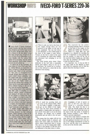
There is only one belt at the front of the engine though there are two grooves in the pulley on the end of the crankshaft. The one belt drives the alternator, as the coolant pump at the front of the engine is gear driven. Tension on the belt is made in the usual way by loosening the clamp bolts holding the alternator and swinging it on its mountings.
The usual tension gives about 12mm deflection of the belt with a reasonable thumb push halfway along its run up to the alternator. Be careful not to overtension as this will lead to a short life for the alternator front bearing.
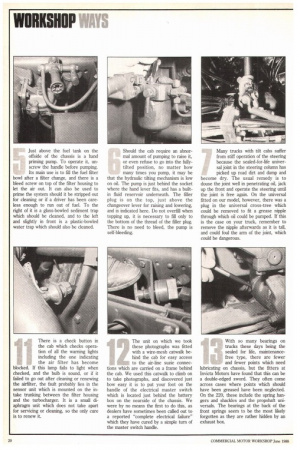
A small but puzzling fault can occur on the exhaust brake. When the brake is applied, a small plunger on the offside of the engine near the back moves forward to push against a sloping plate and operate a fuel cut-off. If the plate is set too far from the plunger, the plunger rod is pushed downwards and can stick in the out position.
This means that the engine will not run when the exhaust brake is released, and fitters have been called out because the driver cannot understand what is wrong. The cure is to set the sloping plate slightly nearer to the plunger so that the rod is not deflected to the point where it sticks. The reservoir for the powersteering hydraulic fluid is mounted on the front of the engine on the offside just behind the alternator. There is a large filler cap, and alongside it is a dipstick for checking the level. It is important to avoid getting dirt into the system, so clean off the top of the reservoir before topping up, and make sure that all containers and funnels used to hold the fluid are clean.
It is important, too, to top up only to the upper mark on the dipstick to leave room both for expansion and for fluid displaced when the steering is turned.
Complaints of lack of power or lack of full revs can often be traced to a stretched throttle cable. The check for this is to push the throttle pedal in the cab down to the floor and check this lever at the back of the fuel pump. It should be right forward touching a stop which is wired to prevent adjustment.
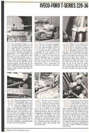
If the lever stops before it reaches the stop, there are two adjustments. One is a left and righthand threaded rod in the section of the linkage immediately in front of the lever, and the other is an adjustment at the end of the throttle cable. Just above the fuel tank on the offside of the chassis is a hand priming pump. To operate it, unscrew the handle before pumping. Its main use is to fill the fuel filter bowl after a filter change, and there is a bleed screw on top of the filter housing to let the air out. It can also be used to prime the system should it be stripped out for cleaning or if a driver has been careless enough to run out of fuel. To the right of it is a glass-bowled sediment trap which should be cleaned, and to the left and slightly in front is a plastic-bowled water trap which should also be cleaned. Should the cab require an abnormal amount of pumping to raise it, or even refuse to go into the fullytilted position, no matter how many times you pump, it may be that the hydraulic tilting mechanism is low on oil. The pump is just behind the socket where the hand lever fits, and has a builtin fluid reservoir underneath. The filler plug is on the top, just above the changeover lever for raising and lowering, and is indicated here. Do not overfill when topping up, it is necessary to fill only to the bottom of the thread of the filler plug. There is no need to bleed, the pump is self-bleeding. Many trucks with tilt cabs suffer from stiff operation of the steering because the sealed-for-life universal joint in the steering column has picked up road dirt and damp and become dry. The usual remedy is to douse the joint well in penetrating oil, jack up the front and operate the steering until the joint is free again. On the universal fitted on our model, however, there was a plug in the universal cross-tree which could be removed to fit a grease nipple through which oil could be pumped. If this is the case on your truck, remember to remove the nipple afterwards as it is tall, and could foul the arm of the joint, which could be dangerous. The gearchange linkage on the 220 runs right across the top of the engine, and is a telescopic rod which extends when the cab is tilted. When it is fully extended, the rod is very vulnerable to bending and, unfortunately, is in an ideal position for fitters to use it as a hand hold to hoist themselves up when working on the engine — and they sometimes do, despite a warning notice in four languages. If the sections of the rod are bent they will not telescope properly, and lowering the cab without realising this will only buckle them more so that the rod will probably need replacing. Slight distortion can usually be straightened. Because of European Community 'eat your own fumes' regulations, the engine-breathing system on the 220 is a closed system. The breathing pressure is controlled by a diaphragm in a unit mounted on the nearside of the engine which can be recognised by a ring of six bolts round the top of the diaphragm cover. In the service manual it lays down that the diaphragm under the cover should be changed at every service. Failure to do so can lead to back-pressure and to unnecessary contamination of the oil through condensation. While we were looking at this engine, on a new truck awaiting its pre-delivery inspection, we spotted a fault which admittedly should not have been there, but which indicates how easily a mistake can be made. The main wiring loom for the engine runs down the nearside near the front, and is clipped to a bracket about halfway down. In this case, the bracket was either distorted or had been fitted the wrong way round so the loom was too far out from the engine block. It had been caught by the edge of the cab floor which had worn the insulation away, and there were signs of arcing.
There is a check button in the cab which checks operation of all the warning lights including the one indicating the air filter has become blocked. If this lamp fails to light when checked, and the bulb is sound, or if it failed to go out after cleaning or renewing the airfilter, the fault probably lies in the sensor unit which is mounted on the intake trunking between the filter housing and the turbocharger. It is a small diaphragm unit which does not take apart for servicing or cleaning, so the only cure is to renew it.
ill:714 The unit on which we took
these photographs was fitted with a wire-mesh catwalk behind the cab for easy access to the air-line suzie connec tions which are carried on a frame behind the cab. We used this catwalk to climb on to take photographs, and discovered just how easy it is to put your foot on the handle of the electrical master switch which is located just behind the battery box on the nearside of the chassis. We were by no means the first to do this, as dealers have sometimes been called out to a reported "complete electrical failure" which they have cured by a simple turn of the master switch handle. With so many bearings on trucks these days being the sealed for life, maintenancefree type, there are fewer and fewer points which need lubricating on chassis, but the fitters at Invicta Motors have found that this can be a double-edged sword. They often come across cases where points which should have been greased have been neglected. On the 220, these include the spring hangers and shackles and the propshaft universals. The bearings at the back of the front springs seem to be the most likely forgotten as they are rather hidden by an exhaust box. Because the bogie on the 220 is air-suspended, there is not a conventional load-sensing valve with a linkage; the load sensing is controlled pneuma tically by the suspension pressure being linked to the air brake pressure. This means that there is no way that an operator can check the working of the load sensing in his own workshops. It requires specialised, and costly, equipment to do this, plus a set of gauges and the chart of the proper pressures at various parts of the system. Definitely a job which should be left to the Iveco Ford dealer. We had to move across to another truck in Invicta's workshops to take this photograph of the breather valve on the gearbox. On the vehi cle: we were working on, the catwalk across the back of the cab completely shielded the breather which not only made it impossible to photograph, it meant that it could easily be forgotten by a fitter carrying out a service without the proper check list. It is essential to check at regular intervals that this breather valve is free, otherwise pressure can build up in the gearbox which will eventually blow some of the seals.
On the back of the chassis is a band-operated valve which is most useful for raising or lowering the suspension so that trailers with the rubbing plate at different heights from the ground can be picked up without jerking or bouncing. At each service you should check that the system is returning to normal ride height and is balanced across the chassis. At each side of the chassis is a small slotted bracket, and if a drill or thin rod is passed through this with the control valve at normal ride height, the rod should pass into a hole in the hexagon underneath. If it doesn't, it means chocking the chassis and resetting.
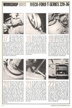
The cold weather assistedstart system on the 220's engine is not a glow plug to each cylinder, it is one glow plug, or igniter plug, fitted in the air intake manifold on the nearside of the engine. Above it, and linked to it by a pipe, is a small reservoir of fuel. When the cold-start is operated, the system sprays fuel into the manifold which is then ignited by the plug thus forming, in effect, a miniature blowlamp inside the manifold to heat up the air. Should the engine be reluctant to start in cold weather, check that the igniter plug is operating, and that the system is spraying fuel. Like the breather for the gearbox, the breather for the rear axle on the 220 is well hidden, not by a catwalk but by suspension linkage and chassis members. You can just see it here, looking like a little round button in the middle of the photograph towards the bottom. As with the breather on the gearbox, it is essential that this breather on the axle casing is kept clear otherwise pressure will build up inside the casing as the air inside heats up, and this will force oil past the hub seals and on to the rear brake linings. On the back of the differential casing is a bracket carrying a wire which runs up to an air valve on the chassis. This is the cut-out safety control when the suspension control lever is being used to raise the rear of the chassis. When the air bags reach their full height, the wire should operate the valve and cut the supply of air to the bags. It is important to check both the security of the wire and the operation of the valve at each service as, should the valve fail to operate, it is possible to force so much air into the suspension bags that they fail. The slot in the bracket is for adjustment.
On the brake back-plates there are inspection holes covered by rubber plugs through which the wear of the brake linings can be checked. Some linings have colour-coded marks on their edges to judge the amount of wear, but others are plain and should be renewed when they reach the minimum thickness laid down in the workshop manual. It is important to replace the rubber plugs securely in the holes after checking as if the holes are left open, road dirt and water can get inside the drums. This will not only shorten the life of the linings, it could make the release operation stiff. As the clutch on the 220 is air assisted, it is impossible to judge the setting of the linkage by free play at the pedal. The free play has to be set in the linkage underneath the vehicle. The proper way to set up the linkage is first to disconnect the air supply so there is no pressure in the system, then slacken off this locknut on the operating rod. Then extend the rod by screwing it out till all free play has been taken up. Then set the nut along its thread 16min from the end of the rod, screw the rod back along the thread to met the nut and lock it up. Access to the points under the front grille needing routine daily checks could hardly be easier. At the top left here is the reservoir for the hydraulic clutch fluid, and in the centre above the radiator are, on the left the reservoir for the windscreen washers and, next to it, the translucent plastic header tank for the cooling system. The engine oil dipstick is lower down on the righthand side of the radiator, and the oil filler is below the front bulkhead to the left of the radiator. This is almost horizontal, and needs either a funnel or a can with a spout for topping up.