


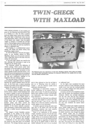
TWO INDICATIONS of axle loading are given by the Maxload
Page 42
If you've noticed an error in this article please click here to report it so we can fix it.
axle-load device. One is a reading on a dial, the other a positive go/no-go signal using a green and .a red light. The green light is illuminated when the axle load approaches within a pre-set percentage of the plated axle weight; when the plated weight is reached or exceeded the red light shows. If the red light comes on while the green one is lit, this means the axle has reached its plated or calibrated load.
Over-loading to a predetermined sensor setting will isolate the starter switch, thus preventing engine restart.
To test the Maxload, CM took the opportunity to use facilities offered by SGB, Mitcham, Surrey, an own-account operator with a large fleet which at the time was evaluating the instrument.
A two-axle rigid vehicle was used for the test, although the instrument is said to be suitable for all vehicle types.
The Maxload utilizes the deflection of vehicle springs which occurs under load; movement of the axle relative to the chassis is converted to an angular movement of the centre spindle of each axle-load sensor. Two axle-load sensors/programmes are considered adequate for most applications and each sensor can give continuous readings at its respective dial and indicator lights.
The rear-axle sensor is fitted to a universal cross-member (supplied) which is mounted between the chassis members above the rear axle. At the front axle, a sensor mounting bracket is provided, and an adjustable linkage connects the sensor to its axle.
Fitted to the centre spindle of the sensor is a variable-resistance contact arm which moves across a fixed, wound resistance and so causes a needle to move on the indicator dial; the needle reveals the approximate proportion of the plated axle weight which is acting on the axle. The centre spindle also carries a three-lobe cam which makes or breaks three sets of adjustable contactbreaker points and these control the illumination of the indicator lights and the isolation of the starter solenoid, automatically preventing a vehicle being started when the axle is loaded beyond a predetermined figure.
The design's in-built flexibility permits movement in the setting of the contactbreaker points relative to the cam, so the sensor can be bench-set so that the lights come on at the required axle loadings.
Calibration of the unit involves loading the vehicle so that each axle is at its plated maximum. The linkage between sensor and axle is then adjusted so that the red light is just on or flickering when the vehicle is rocked — and the indicator needle will be calibrated simultaneously.
Interchange of semi-trailers requires no further calibration of the sensors fitted to either unit or trailer. To settle the road springs before each reading we drove lyd forwards, 1 yd backwards, and braked sharply after each manoeuvre.
For our tests, the Maxload was calibrated with front axle loaded to 3 tons 6 cwt 3 qtr, and the rear axle 7 tons 10 cwt 1 qtr. Our object was to find the smallest overload that would register on the instrument.
It became apparent during the early readings that at the plated axle load the light illumination response was more sensitive and accurate than the dial reading.
There is no calibration at the unladen weight, therefore accuracy for the dial reading may be claimed only at the axle plated weight. When at its maximum deflection the needle did not cross into the shaded overload area on the dial; in, regardless of whether the axle was at its plated weight or above, the needle indicated the axle to be at its plated or calibrated load.
As the lights were considered the more accurate method of load indication and the needle never went into the overload shaded area, no needle readings have been given in the accompanying tables.
Accuracy proved to be completely acceptable with the lights; the maximum overload obtained, without any red-light indication, was the rear axle, and the error obtained was only 1.5 per cent of the calibrated axle weight. For each error obtained, the instrument read low. An overload of 8.75 cwt on the rear axle rendered the starter motor inoperative.
When total plated axle weights exceed the gross vehicle weight there is no method for converting each load reading to actual figures, so the load on each axle may be below its plated maximun even though the plated gross vehicle weight may be exceeded.
The instrument is marketed by Specialised Instruments Ltd, Bank Chambers, 2 Bridge Street, Leatherhead, Surrey, which says that it can easily be fitted within eight hours by one man. The price for two sensors, instrument head and fitting kit is less than £70.