


Obtaining "Neutral" in r a Torque Converter
Page 58
If you've noticed an error in this article please click here to report it so we can fix it.
HYDRAULIC torque-converters of the Fottinger type will not entirely cease to transmit power even at low speeds, and when used in conjunction with a gearbox this condition may cause difficulties when changing gear. It is therefore usual to arrange for some positive form of disconnection such as a clutch, which, however, adds to the expense. Patent No. 634,948. shows a modification which is said to give a perfectly free position. The patentee is A. B. Ljungstroms Angturbin, Stockholm.
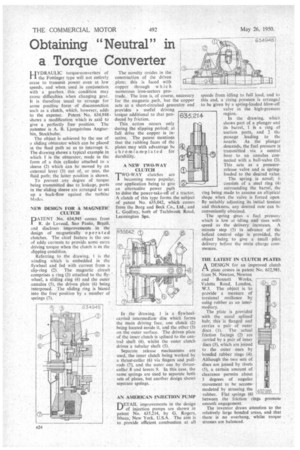
The object is achieved by the use of a sliding obturator which can be placed in the flied path so as to interrupt it. The drawing shows a typical example in which 1 is the obturator, made in the form of a thin cylinder attached to a sleeve (2) which can be moved by an external lever (3) out of, or into, the fluid path; the latter position is shown.
To prevent any degree of torque being transmitted due to leakage, ports in the sliding sleeve are arranged to set up a back-flow against the turbine blades.
NEW DESIGN FOR A MAGNETIC CLUTCH
PATENT No 634,945 comes from R. de Lavaud, Sao Paulo, Brazil, and discloses improvements in the design of magnetically o p e r a ted clutches. The chief feature is the use of eddy currents to provide some extra driving torque when the clutch is in the slipping condition.
Referring to the drawing, 1 is the winding which is embedded in the flywheel and fed with current from a slip-ring (2). The magnetic circuit comprises a ring (3) attached to the flywheel, a sliding ring (4) and the outer annulus (5), the driven plate (6) being interposed. The sliding ring is biased into the free position by a number of springs (7). The novelty resides in the construction of the driven plate; this is faced with copper through which numerous iron-sectors protrude. The iron is, of course, necessary for the magnetic _path, but the copper acts as a short-circuited generator and provides a useful driving torque additional to that produced by friction.
This action occurs only during the slipping period; at full drive the copper is inactive. The patent mentions that the rubbing faces of the plates may with advantage be chromium-plated for durability.
ANEW TWO-WAY CLUTCH
TWO-WAY clutches are I becoming more popular, one application being to give an alternative power path to drive the power-take-off of a tractor. A clutch of this type forms the subject of patent No. 635,042, which comes from the Borg and Beck Co., Ltd., and L. Godfrey, both of Tachbrook Road, Leamington Spa.
In the drawing, 1 is a flywheelcarried intermediate disc which forms the main driving face, one clutch (2) being located inside it, and the other (3) on the outer surface. The driven plate of the inner clutch is splined to the central shaft (4), whilst the outer clutch drives a tubular shaft (5).
Separate release mechanisms are used, the inner clutch being worked by a thrust-collar (6) via fingers and pullrods (7), and the outer one by thrustcollar 8 and levers 9. In this case. the same springs are used to separate both sets of plates, but another design shows separate springs.
AN AMERICAN INJECTION PUMP
DETAIL improvements in the design of injection pumps are shown in patent No. 635,214, by G. Rogers, Ithaca, New York, U.S.A. The aim is to provide efficient combustion at all
speeds from idling to full load, and to this end, a rising pressure is arranged to be given by a spring-loaded blow-off valve in the high-pressure region.
In the drawing, which shows part of a plunger and its barrel, 1 it a ring of suction ports, and 2 the passage leading to the nozzle. As the plunger descends, the fuel pressure is transmitted via a central bore to an annulus connected with a ball-valve (3). This acts as a pressurerelease valve and is springloaded to the desired value.
The spring is novel; it consists of a steel ring (4) surrounding the barrel, the ring being made to assume an elliptical shape when the valve is forced open. By suitably adjusting its initial tension and thickness, any desired rate can bL conveniently obtained.
The spring Oyes a fuel pressure which is low at idling and rises with speed as the delivery increases. A minute step (5) in advance of the helical control edge is provided, the object being to give a small pilot delivery before the main charge commences.
THE LATEST IN CLUTCH PLATES A DESIGN for an improved clutch
plate comes in patent No. 632,985. from N. Newton, Newton and Bennett Works, Valetta Road, London, W.3. The object is to provide a measure of torsional resilience by using rubber as an intermediary.
The plate is provided with the usual splined hub; this is flanged and carries •a pair of outer discs (1). The actual friction facings (2) are carried by a pair of inner discs (3), which are joined to the outer ones by bonded rubber rings (4). Although the two sets of discs are joined by rivets (5), a certain amount of clearance permits about 3 degrees of angular movement •to he accommodated by stressing the rubber. Flat springs (6) between the friction rings promote smooth engagement.
The inventor draws attention to the relatively large bonded areas, and that there is no overhang, whilst torque stresses are balanced.