


MANUFA
Page 46
Page 47
Page 48
If you've noticed an error in this article please click here to report it so we can fix it.
:TURING
centrifuc
ily cast
PISTOI\ RINGS
The Methods Employed by the British Piston Ring Co., Ltd., Involving the Use of Highly Scientific Machines Processes That Make for Efficiency and Reliability in a Delicate Item of Motorvehicle Engine Equipment
ALTFIOUGH, to the average user of commercial vehicles, the piston ring may seem but a simple component to produce, in reality it is one which requires much research work and care in its manufacture if it is to give good service under arduous conditions. As we know that many of our readers take a keen interest in how the component parts of their vehicles are produced, we recently visited the works of the British Piston Ring Co., Ltd., at Coventry, to examine the methods employed in making the wellknown Brico rings.
The manufacture of piston rings begins in the laboratories, both physical and chemical, where all supplies of pig-iron are tested and selected to form the most suitable mixture giving strength, elasticity and durability. After this, the method of casting is the most important matter to decide. In the ease of Brico rings, the company has decided in favour of centrifugally chill-cast tubes or pots, from each of which a number of rings can be produced by boring, turning and parting off.
Metal Distributed by Centrifugal Force.
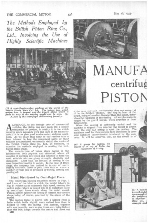
The centrifugal-casting machines shown in Figs. 1 and 2 are of the kind in which the mould (shown in Fig. 9) rotates at an extremely high speed, causing the molten metal which is poured into it to distribute itself by centrifugal force evenly along the metal mould. Thus a hollow cylindrical casting is formed, the outside shape being, of course, governed by the shape of the mould.
The molten metal is poured into a hopper from a ladle which bolds slightly more melted iron than is needed to form the casting. The surplus, together with any impurity, such as slag dross, etc., being lighter than the iron, keeps towards the centre and flows out B32 of the open end and, consequently, does not appear at all in the finished product. The ring in front of the mould, being of smaller diameter than the latter, determines the thickness of the casting. All surplus metal is caught by the guard shown, which prevents it from flying about. When the casting is sufficiently cooled and the machine is stopped from rotating, the mould is drawn back, the disc (A) acting to eject the casting. The machines used for this purpose have embodied in them some patented improvements introduced by the company. It will be observed that, as the mould is of metal, there is no possibility of defects through sand inclusions. Moreover, as the rate of cooling is relatively high, the material is exceedingly close-grained and, consequently, has excellent elastic properties.
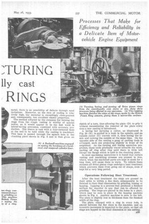
The method adopted by the company for turning the rings from the rough casting is worthy of special notice, as it would appear to be the last word in labour-saving processes, combined with accurate production. The sleeve is cast with a four-cornered base at the end to be held while the casting is machined. This base is passed through the square hole in the chucking plate shown in Fig. 3 and is then given an eighth a a turn, thus allowing the plate (D) to grip it without necessitating the removal of the plate every Lime a new casting is introduced.
A boring bar carrying a cutter, as illustrated in Fig. 10 (B), is guided in a bush in the spindle, and an outside cutter (C) travels with it, thus boring the inside and turning the outside at the same time. On the opposite side of the casting a gang of parting tools is arranged, each one projecting slightly in front of its neighbour. As the turning and boring operation progresses, these tools gradually travel towards the work, parting off ring after ring until there is little left except the flange which is held in the chucking plate.
In most machining operations it is found that certain casting and machining stresses are present in Iron, which, when the machined parts are kept in stock for a long time, will cause them to warp. To relieve these stresses all Brico piston rings undergo a heat treatment which prevents them from going out of shape, even if kept for a very long period.
Operations Following Heat Treatment.
After the heat treatment the rings are ground on their sides to within a tine limit, subsequently to be finished to their final dimensions by grinding, honing or lapping. Lapping is a process that produces a finished surface far superior to any that can be effected by grinding. The rings are placed in the holes in a plate, which may be seen in place in the lapping machine shown in Fig. 4. Another machine is seen to the left. The plate is slightly less in thickness than the finished width of the ring.
The plate, charged with a ring in every hole, is placed between the flat discs in the machine, and an eccentric movement is imparted to the plate, so that all rings are lapped to the final dimension at one setting. When a ring is slit with a fine saw, it is necessary that something should be done to give it the required spring, to ensure its exerting the correct pressure against the cylinder wail to enable it to prevent gases from passing it. In the case of rings made by the British Piston Ring Co., Ltd., this is done by what is known as internal hammering, which consists of forming fa number of indentations on
the inside of the ring, the deepest FRONT being opposite the split and dying INSIDE
away towards the free ends.
This process has the effect of widening the gap made by the saw ; several of the rings are then placed in a sleeve, which contracts them until the ends of the split meet. While in this sleeve, they are clamped together between the flanges of the mandrel shown in Fig. 5, so tightly that the sleeve can be removed. The periphery is then ground in a machine to the diameter of the cylinder in which the rings are eventually to be used. When the flanges are made to release their hold the rings fly to their free dimension and shape.
One of the most important features necessary in a piston ring is that it should leave no space between it and the walls of the cylinder in which It is to work. Another important point is that its spring pressure against the cylinder walls should be even at all parts of the ring. To ensure the correct form of the rings when compressed, they are placed separately in the gauge shown in Fig. 6, which consists of a ring of hardened steel ground to the exact diameter of the cylinder. This ring rests on two rollers, so that it can gradually be turned around by the operator.
A slot is formed in the body of the device at E, with a diffused light behind it. By this means, the examiner can detect the smallest possible space, should one occur, between the ring and the gauge. No piston ring is allowed to pass unless it completely cuts off all light.
Piston rings must obviously be of strong material to withstand the hard work that they have to perform and they should be able to retain their elasticity, so as to preserve their original pressure against the cylinder walls. Another point is that, after being sprung over the piston, so that they can enter their grooves, the rings should have sufficient elasticity to return to their original dimension. Should they suffer permanent deformation their efficiency will be impaired. Far greater attention is paid to this feature than was the case in the past.
The Brico method of testing for these characteristics is to make the test on an actual ring, and not on a piece cast especially for the purpose. That method has been found to be of little value, especially in the ease of centrifugal castings. For the strength test, the ring is placed on tile knife edges shown in the machine in Fig. 7. The weight is then moved along the arm until the actual breaking point is reached. From the breaking load, the transverse breaking strength and equivalent tensile strength are calculated.
To revert to the question of forming piston rings so that they exert a uniform pressure against the cylinder walls, methods other than internal hammering are known, such as shaping under heat. The British Piston Ring Co., however, normally adheres to the hammering method, except in the case of rings that are hardened and tempered, in which case the desired shape is obtained in the hardening operation.
The heat treatment of piston-ring material to secure much greater hardness than is normally obtainable in the case of material which must of necessity be machinable, is an important development. The uniformly close grain obtainable in centrifugal castings forms a base material on which subsequent hardening and tempering can be carried out with consistent results.
Results so far obtained indicate that hardened and tempered piston rings are of considerable help in connection with cylinder wear, especially when the cylinder liners themselves are of hardened and tempered centrifugally east iron.
PLATE PEC.ULATES kor C APING
The fallacy that rings should not be harder than the cylinder has been ei.ploded long ago. In considering the matter, one has to think only of the wearing surface of the ring compared with that of the cylinder. It has, however, been proved that rings of a comparatively soft nature hold metallic and siliceous particles, which cause abrasion of the cylinder walls. Properly hardened and tempered rings do not hold these particles embedded in the same way. "
Liners for cylinders, both of the "wet" and the " dry " kinds, are made by the company, all of which are cast by the centrifugal process, the same care being taken in the selection of the most suitable mixtures of iron.
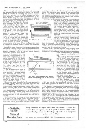
Fig. 8 shows a hardness test being made by a Rockwell machine on a hardened and tempered cylinder liner. In this machine the diamond cone is brought into contact with the surface of the component to be tested, then pressure is brought to bear upon the diamond and the depth to which it enters the part under a known load is an indication of the hardness, as the softer the material the deeper will the cone penetrate. The distance the diamond bites into the iron is recorded on tile dial, and extreme precision is obtained in the reading. This is one of the most exact machines employed in the whole procedure.