


&amine11 Design for a Refuse Collector
Page 54
If you've noticed an error in this article please click here to report it so we can fix it.
DATENT No.. 595.516 tomes from P.
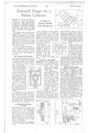
Hugh, L. Watts and Scammell Lorries, Ltd. Folea.s Lane, Watford, and describes a refuse-collecting body arranged to tin rearwards to discharge the contents the scneme is intended mainly for bodie; carried by semitrailers and hauled by the mechanical horse.
The drawing shows the body in the
tipped position The entire body is pivoted on trunnions it) at the rear, whilst the end (2), which normally functions as a loading receptacle, is also pivoted about a point (3): A pair of cables runs from the ends (4) to a fixed anchorage (5) In the frame, the object being to open the rear portion of the body when it is lifted.
The body is tipped hydraulically by a ram (6) powered by an engine-driven pump. Cylinder 7 contains a powerful spring, which gives the body a start on its return stroke, and expedites the movement.
OIL COOLING FOR PISTONS
ASYSTEM for circulating cooling oil around the under side of a piston is described in patent No. 594,965, by A. Morris and R. A. Lister and Co., Ltd., Victoria Iron Works, Dursley, Glos. It demands no
additional parts and calls for only slight modifications to the usual parts.
Oil from the lubricating system passes through a bore in. the centre of the connecting rod to the gudgeon-pin bush. The piston is provided with a cored chamber (1), which is completely closed except for a rectangular orifice 2) in its base. This is machined to suit the radius of the top Of the connecting rod and the latter just enters the chamber.
In operation, a jet of oil from the port (3) sprays the under side of the piston crown. preferably on the down stroke. On the up stroke 'the heated oil can escape through the slight clearance between the connecting rod and the chamber door. In both vases the natural inertia is of assistance.
A PERMANENT-MAGNET . DYNAMO
ALTHOUQH used for many years on motorcycles, permanent-magnet generators have been insufficiently powerful for cars and larger vehicles. With the advent of the modern magnet alloys, however, this is no longer the case, and patent No. 594,413, from the Raleigh Cycle Co., Ltd., and W. Brown, both. of Nottingham, shows a larger dynamo of this pattern.
The drawing shows the generator built into a motorcycle engine, although is;36
it may be applied to heavier vehicles. No extra bearings are needed, the permanent-magnet rotor (1) being carried on the crankshaft, a feature Which permits the use of .an air gap of 0.005 in. T he stator comprises a coil
(2), complete with iron-path members (3), all of which are housed in a cast extension of the crankcase.
The output is alternating current, but can be modified to charge the batteries by means of a rectifier having no moving parts. The great advantage is the total absence of wearing parts, such as brushes and rotating conductors.
LATEST IN STEAMERS
RESEARCH into the design of steam vehicles is still proceeding, as is demonstrated in patent No. 594,428, which comes from Stanley Steam Motors Corporation, Chicago, Illinois, U.S.A.
The drawing gives a diagrammatic view of the layout employed. The flash-type boiler (1) is oil fired and supplies steam through a valve (2) to the engine (3). The exhaust steam from the engine drives a turbine (4) and pre-heats the boiler-feed water as it passes through an exchanger (5). Condensate is led to a reservoir (6), whence it is returned to the boiler by two pumps (7).
The action of the two feed pumps forms the basis of the patent, One is positively driven by the engine and the other by the exhaust turbine, with a free wheel (8) between them so that the turbine can overrun. Each pump is electrically controlled, as is a motordriven blower (9) for the oil-burner, which can, alternatively, be driven by the exhaust turbine through another fr-e wheel should the turbine speed be greater than that of the motor.
Both pumps are arranged to be responsive to both boiler temperature and pressure; this is to ensure that, whilst ample steam is -available at all times, there will be no dangerous pressure set-up. The pressureresponsive device is arranged so that at a predetermined pressure the electromagnetic contact to the water-supply pump is broken, which prevents water being fed to the boiler. With the contacts closed, the pump again comes into operation.
QUICK-ACT1NG JACK
ASIMPLE jacking System for, road vehicles is disclosed in . patent No. 594,424 by H. 'Mottershaw. Manchester House, Feckenham Road, Astwood Bank, Redditch. No manual effort is needed to operate it.
To each brake back-plate is pivoted, at point 1, a rocking lever, the radii's of which is slightly in excess of that of the road wheel. Normally the lever remains in position 2 until it is needed for Use. When it is reqUired to raise the wheel, the lever is temporarily keyed to the wheel by a removable pin and the vehicle is then driven backwards.
The lever is carried downwards and lifts the wheel clear, as shown at 3. The momentum of the vehicle carries the lever over dead centre, and it conies to rest against an ibutinent" (4): The wheel can' as easili be lowered by a reversal of the pro:..-ess..