A Steering Joint with Separate Ball
Page 52

If you've noticed an error in this article please click here to report it so we can fix it.
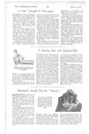
THE use of a separate hardened steel bail is an interesting feature of a new steering ball joint which has been patented by Mr. A. E. Parsons, of A. E. Parsons and Co.. Marsh Mills, Bridge Street, Leominster.
Construction is made clear by the accompanying drawing, from which it will be seen that the joint incorporates a two-piece housing, the lower ,porLion of which is formed in one with the screwed end of the track rod or steering arm. The other steering link is attached to a pin which has a cup-shaped end. The end operates between the tor portion of the housing and the hardened steel ball, and • a spring-loaded socket below the ball serves to take up play.
As the whole design has been planned with the idea of obtaining the maximum area of wearing surfaces, provision for taking up wear (apart from the automatic effect of the springloaded socket) is not normally considered necessary, but for cases where such provision 's regarded as desirable, there is an alternative type in which spring pressure can be increased by means of an adjustable plug in the base of the lower housing. A third form is available, in which the bottom socket is in the form of a hardened steel pressing, and a second hardened steel pressing is inserted in the upper housing, to provide a bearing surface for the outer face of the upper ball socket.
In addition to long life, safety is claimed as an advantage of the design. The joint cannot fall apart as a result of excessive wear brought about by prolonged neglect, as the cup-shaped end of the ball-socket pin is larger than the hole in the upper housing.
The joint is also suitable for use in conjunction with steering and suspension designs in which a large degree of angularity is called for, approximately 20 degrees of movement on each side of normal being permitted in a plane at right angles to the ordinary rotary steering movemerr.


