


Reducing the Length of
Page 54
If you've noticed an error in this article please click here to report it so we can fix it.
Injection-pump Piping
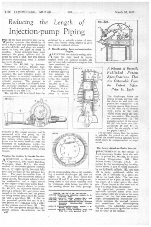
WITH the high pressures used in inW jection systems, the elasticity of even a thick pipe can sometimes cause an after-dribble, and steps are usually taken to keep the pipes as short as possible. Some designers have even arranged the pump cylinder and injector to form a unit, but this means excessive dismantling when a nozzle has to he changed.
Patent No. 461,398, by JunkersMotorenbau G.m.b.H., Dessau, Germany, reveals an attempt to unite the good points of both systems. In the drawing, the unit injection pump of each cylinder is mounted immediately above it, being housed in a bore in the cylinder casting. The plunger is operated by a rocker (2) worked from the overhead camshaft, whilst output control (helical-edge type) is given by movement of an arm (1).
The injector (3) is screwed into the cylinder in the normal manner, and is connected with the pump by the shortest possible length of pipe. By this means, either pump unit or injector can be easily removed with the minimum of disturbance, whilst the complete system does not unduly protrude beyond the general outline of the engine.
Varying the Ignition by Intake Suction.
ACCORDING to Moore Inventions Corporation, 946, Slater Building, Worcester, Mass., U.S.A., the usual method of automatic-ignition control, that is, by engine speed, does not fully take into account all the relevant factors. The most favourable form of control would give maximum retard at idling speeds, maximum advance during acceleration, and a slight retard as the engine torque rises under load.
The above concern shows, in patent No. 461,077, an improved scheme employing a cylinder (4) and piston connected to the intake suction, the piston rod being formed into a rack (3) meshing with a gearwheel (2). A disc on the gearwheel spindle has cut in it a cam-groove (5), engaging with a roller on the ignition control lever (1). The use of the cam-groove means that any desired ignition characteristic can be A36 obtained by a suitable choice of contour, that shown being stated to give the control outlined above.
A Double-acting Internal-combustion
Engine.
A LTHOUGH the double-acting prinrt ciplc has been used in steam engines from the earliest models, its use for internal-combustion engines has been restricted to the largest types of stationary units. A scheme applying this principle to the smaller sizes forms the subject of patent No. 461,302, by R. D. Young Millbrae, California, U.S.A.
This scheme employs a crank driven reciprocating sleeve (4) containing a central diaphragm (6) and an upper lid (3). The two piston-like members (5 and 7) do not reciprocate, being fixed to the outer cylinder wall by trunnions, slots being provided in the moving sleeve for their passage. The diaphragm forms the piston proper, moving with . its sleeve to and from the piston-like obturators. The working spaces thus formed are fed with air or mixture from ports in the wall, whilst other ports are used for evacuation. The supplyis precompressed by the pumping action of the upper lid (3); this forms two compartments (8 and 9), to which the air supply is led via pipes 1 and 2.
The inventor states that the system is suitable for petrol or oil engines, whilst the double-acting principle lends itself easily to compressed-air arrangements.
The Latest American Brake Practice.
IMPROVEMENTS in the design of
sclf-energizing brakes form the subject of patent No. 461,284, by 13endix Aviation Corporation, 105, West Adams Street, Chicago, U.S.A. Referring to the accompanying drawing, which shows a pair of shoes expanded by an hydraulic cylinder (1), one shoe. ((1) is freely positioned, whilst the other (3) is anchored to ,a pivot pin (4) in the back plate. The free shoe is connected by a pair of links (5) to the other, at a point above the pivot pin. These impart to the lower end of shoe 6 a small radial movement.
In operation, pressure from the hydraulic cylinder forces both shoes into contact with the drum in the usual manner, but the free shoe executes a slight circumferential movement also, which increases the mutual • pressure and constitutes the self-energizing member. T!_,e adjustable snail-cams (2) are used to make up the lost motion due to wear of-the linings.