


A New Injection Pump from America
Page 49
If you've noticed an error in this article please click here to report it so we can fix it.
Orthodox in General Design but Incorporating Ingenious Adfusting Devices and Special Materials THREE years of laboratory development, plus a full 1 year of practical testing, preceded the recent announcement of a high-speed solid-injection fuel pump for compression-ignition engines by the American Timken rollerbearing company. At present the pumps are being made in two sizes for one, two and six-cylindered engines. Type A, which uses plungers of from 4 ram, to 9 mm. diameter, is adapted for engines up to approximately 150 b.h.p., and operates at speeds up to about 4,000 r.p.m. Type B is intended for engines from 110 b.h.p. to 250 b.h.p.
As will be seen from the accompanying drawings, the pumps are of the cam-operated, helical-plunger type and
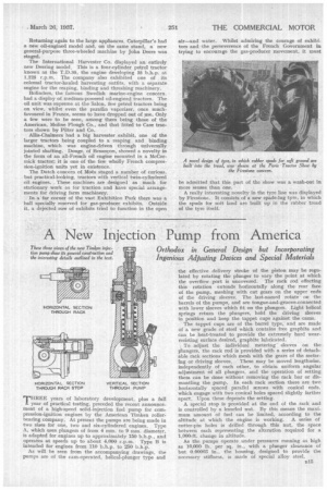
the effective delivery stroke of the piston may be regulated by rotating the plunger to vary the point at which the overflow port is uncovered. The rack rod effecting this rotation extends horizontally along the rear face of the pump, meshing with cut gears on the upper ends of the driving sleeves. The last-named rotate on the barrels of the pumps, and arc tongue-and-groove-connected with lower sleeves which fit on the plungers. Light helical springs return the plungers, hold the driving sleeves in position and keep the tappet cups against the .cams.
The tappet cups are of the barrel type, and are made of a new grade of steel which contains free graphite and can be heat-treated to provide the extremely hard wearresisting surface desired, graphite lubricated.
To adjust the individual meteringsleeves on the Plungers, the rack rod is provided with a series of detachable rack sections which mesh with the gears of the metering or driving sleeves. These may be moved lengthwise, independently of each other, to obtain uniform angular adjustment of all plungers, and the operation of setting them can be done without removing the rack bar or dismantling the pump. In each rack section there are two horizontally spaced parallel screws with conical ends, which engage with two conical holes spaced slightly farther apart. Upon these depends the setting.
A special stop is provided at the end of the rack and is controlled by a knurled nut. By this means the maximum amount of fuel can be limited, according to the altitude at which the engine is working. A series of cotter-pin holes is drilled through this nut, the space between each representing the alteration required for a 1,000-ft. change in altitude.
As the pumps operate under pressures running as high as 10,000 lb. per sq, in., with a plunger clearance of but 0.00003 in„ the housing, designed to provide the necessary stiffness, is made of special alloy steel,