


A New Method of
Page 80
If you've noticed an error in this article please click here to report it so we can fix it.
GEAR RECTIFICATION. t'
IN their specification, No. 305,971, Frederick William Lanchester and Lanchester's Laboratories, Ltd., describe a new method of rectification of gears that have been well formed, but may still possess minute inaccuracies due to slight errors in cutting the teeth or through warping during the hardening process. It must be understood that such a process as that described. is not intended to correct errors
a pronounced character.
To understand the process, one must not in any way confusd it with the well-known but unsatisfactory process of grinding-in by running one wheel against another having a brake resistance, as in the present plan no brake of any kind is employed.
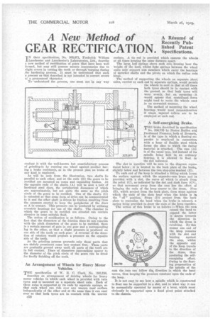
As will be seen from the illustration, two shafts lie parallel to each other, and at the ends (B) the gears to be rectified are mounted on cones mid expanding bushes. At the opposite ends cf the shafts (A) will be seen a pair of hardened steel discs, the peripherical diameters, of which are approximately, but not quite the same as the pitch circle of the gears to be rectified. One of the shafts (C) is extended so that some form of drive can be communicated to it and the other shaft is driven by friction resulting from the pressure exerted to keep the peripheries of the discs at A in contact. This pressure can be produced by utilizing eccentric housings for one of the shafts. The chamber in which the gears to be rectified are situated can contain abrasive in some suitable fluid.
The action of rectification is as follows. Owing to the fact that the diameters of the friction discs do not coincide with the pitch diameters of the gears to be rectified, there is a certain amount of gain in one gear and a corresponding lag in the other, so that a slight pressure is produced on one side of the teeth on each gear. A reversal of the direction of rotation would produce a pressure on the opposite side of the teeth.
As the grinding process proceeds only those parts that are unduly prominent come into contact first. These parts are gradually ground away until all parts of the teeth are in full contact. Discs of diameters approaching nearer to the diameter of the pitch circle of the gears can be fitted for finally finishing off the teeth.
An Arrangement of Wheels for Heavy Motor Vehicles.
THE specification of W. E. C. Clark, No. 305,7'56, describes an arrangement of driving wheels for heavy motor vehicles in which each wheel is provided with twin tyres and is mounted on a separate short axle. Each of these axles is supported at its ends by separate springs, so that each wheel can ride over any uneven road surface independently of the other and at the same time it can cant over so that both tyres are in contactwith the uneven surface. A tie rod is provided which ensures the wheels at all times keeping the same distance apart.
The large leaf springs above each axle housing bear tho weight of the lead, whilst light springs between the wheel units only support side members which carry the bearings of sprocket shafts and the pivots on which the radius rods hinge.
The method of supporting the wheels on separate short axles, carried at each end by separate springs, would permit the wheels to cant so that at all times both tyres should be in contact with the ground, so that• both tyres Will wear evenly, but . on cornering • it would appear that centrifugalforce might tend to make the wheels cant
in an unwanted manner. • . The method of mounting the wheel. bearings would need 'reconsideration if single tapered rollers are to be employed at each end.
• A Self-energizing Brake.
riTHE brake described in specification
No. 286,735 by Nestor Baillot and Ferdinand nernaux, both of Brussels, is of the type in which a floating' expander is employed in connection with a hoop of flexible steel which forms the shoe to which the facing material is attached. The cam (A), is of the lisual type, but instead of its spindle being held in an ordinary bearing, it is allowed to float in the slot indicated.
The slot in question will be seen in the diagram reproduced below ; it is located in the back plate of the brake, slightly below and between the two stop-pins marked (E).
To each end of the hoop is attached a fitting which forms the surface against which the expander-cam bears and is provided with a slot, the curve of which is struck from the point (C), as indicated by the dot and dash lines (C1), so that movement away from the cam has the effect of bringing the ends of the hoop nearer to the drum. Pins (E), which project from the back plate, form stops against which the ends of the slots bear when the brake is in the " off " position. Stops (D) project from the back plate to centralize the band When the brake is released, a spring being provided to draw the ends of the hoop together. The action of this brake is as follows :—When the cant causes the band to expand the latter is drawn towards the direction in which the drum is revolving. By this means one end of the hoop remains with its slot end bearing against the stop, whilst the opposite end of the hoop travels in the direction of the drum, thus producing the selfenergizing effect. Owing to the floating propensities of the spindle of the cam the Cam can follow thq, direction in which the band moves, thus keeping the pressure constant upon the ends of the hoop.
It is not easy to see how a spindle which is constructed to float can be supported in a slot, and in what way it can be successfully operated by means of a lever, which must obviously be supported upon a fixed pivot point attachedto the chassis.