


Patents Completed.
Page 36
If you've noticed an error in this article please click here to report it so we can fix it.
ARRANGEMENT OF DIFFERENTIAL GEAR.—Societe Anonyme des Automobiles Peugeot —No. 19,715, dated (under Convention) 22nd September, 1906. —The differential gear is enclosed within a casing (1). A tube (2), through which passes a shaft (3) driven by the shaft (4), forms part of the casing. The shaft (4) transmits motion by means of a ball joint (6) to the shaft (3). The end of the tube remote from the differential casing is in the form of a spherical cup (7) adapted to engage a support (8) carried by a cross arm (9) on the vehicle frame. The hollow axle comprises two parts (10, 11) connected together by means of a bracket member (12) passing round the differential casing and serving to support the same. The differential drives the shaft (16), which is connected to the wheels at 17, through the medium of universal joints (20). The member (12) is provided with an eye (18) through which the tube (2) passes ; the member is also provided with an extension (19) to which the differential gear casing (1) is fixed. The eye (18) is of such size that the joint (6) on the opposite end of the tube (2) can pass through. In this way the differential gear and its oontrolling, or driving, shaft may be dismounted as a, whole, and removed from the rear of the vehicle after the connections have been released, the vehicle being supported by the hollow axle.
CARBURETTER. — Argyll Motors, Ltd.—No. 14,215, dated 20th June, 1907. —This carburetter consists of upper and lower parts connected by an intermediate pipe (A). The lower part consists of an ordinary float chamber (B) provided with
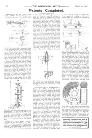
a fuel nozzle (C). The upper part consists of a sleeve (D) which is arranged to slide in a barrel (E) placed in any convenient position in the .inlet pipe (V). The sleeve is provided, at its upper end, with an auxiliary air valve (G) and it terminates at its lower end in a cone-shaped, perforated base (H). Ports (di) are also provided in the sleeve (D) which, when in its raised position, communicates with tee atmosphere. The barrel (E) is provided with ports (e, et). The ports (e) register with holes (f) in the inlet pipe (F), and, when the sleeve (D) is in the position shown, the ports communicate with the inlet pipe (F) by means of an annular recess provided in the sleeve (D). When the sliding sleeve (D) is in the lowest position, communication with the petrol jet (C) is cut off, whilst free communication between the engine and the atmosphere is provided by means of the ports (f, e, el). By raising the sleeve (D), which is done by means of the link (D2) and bell-crank (D3), the communication between the atmosphere and the engine is gradually closed. The further raising of the sleeve (D) establishes communication between the engine and the explosive mixture through the ports or openings (e2) in the barrel (El.
ROAD-R E PAT RT N O AP P A RATUS.— Brodie.—No. 14,794, dated 27th June, I907.—This invention relates to an apparatus for laying a mixture of pitch and sand on a macadam road. Two tanks are arranged on the vehicle (1), the tank (3) containing pitch, and the tank (4) containing sand, or like material. A hopper ii is mounted on the rear of the vehicle into which the pitch flows by means of the pipe (6). A measuring device, consisting of two spur wheels (10) meshing together within a casing (8), is arranged at the end of the pipe (6). The sand in the tank (4) is also conveyed to the hopper through a shute (16) which is provided with a measuring device on the end nearest the hopper. This measuring device consists of a shaft (18) having four vanes (17) mounted thereon. The spur wheels and the shaft are suitably geared together and are driven by a motor (2) which may also be used for propelling the vehicle. A helical stirrer (22), which is arranged within the hopper (5) is adapted to rotate therein and so agitate and thoroughly incorporate the contents. When the sand and pitch have been thoroughly mixed in the hopper (5), they are forced, by means of the helical stirrer (22), through an elbow (28) into a pipe (29). The pipe (29) is provided with
a series of holes along its under face; it is capable of swinging to either side on the shaft (21) through the medium of
the elbow (28). A helical worm (30), which is arranged within the pipe (29), is geared to the shaft (21) through bevel wheels (31) and it is adapted to convey the mixture to the end of the pipe (29). When the mixture is 'first introduced into the pipe (29) the latter is turned so that the holes therein will be presented to the top in order that the mixture may be conveyed along the whole length of the pipe before it is distributed on to the road.
TIRE.—Hill.—No. 4,746, dated 26th February, 1907.—A wheel (1) of ordinary construction is provided with a steel tire (3). The wheel is also provided with an outer tire consisting of wooden blocks (4) held in position by iron frames (5). The space between the blocks (4) is filled with a resilient material such as indiarubber. In the annular space between the inner tire (3) and the outer tire (4, 7) iudiarubber rings (8, 9) are inserted. The outer tire (4, 7) and the indiarubber r ngs (8, 9) are held in position by means of side plates (10, 11) which are secured to the felloe (2) of the wheel by means of bolts (12). The blocks (4), and the composition in the intermediate space (7), are prevented from radial displacement by means of lugs (16, 17) on the frames (5).