


Patents Completed.
Page 32
If you've noticed an error in this article please click here to report it so we can fix it.
Complete specifications of the following patents will be sent to any address in the United Kingdom by the Sale Branch, Patent Office, Holborn, W.C., upon receipt of eightpence per copy.
Electrical Welding of Brass.
N. Prostler and Gesellschaft fill. Elektrotechnische Industrie m.b.H., No. 25,987, dated 12th November, 1912. —It has not hitherto been possible to electrically weld brass or other metals which are good conductors of both heat and electricity, as in the first place it is difficult to ebtain the resistance necessary for heating them, and in the second place such heat as is obtained is readily conducted away. According to this specification brass plates or like metals can be welded by using an electrode pressing vertically on the surface to be welded, with a pressure not exceeding 66 lb. For welding seams, roller electrodes are used, as shown in one of the accompanying figures, and the plates are passed along between them. For other work a rodshaped electrode may be used in conjunction with a roller.
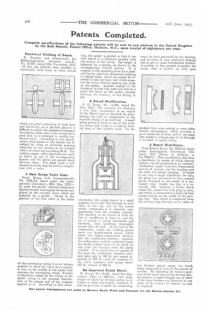
A New Krupp Valve Gear.
Fried. Krupp A.G. Germaniawerft, No. 2132/13, dated under the International Convention, 20th May, 1912.— In some two-stroke internal-combustion engines several scavenging valves are employed in the cylinder cover which are operated by a spider. Owing to the position of the fuel valve in the midst
of the scavenging valves it is not always possible to allow the valve lever exactly to bear on the middle of the spider that operates the scavenging valves. Trouble is therefore caused by the tilting of the spider owing to the unequal distribution of the masses and of the pressure applied.to it. According to this inven tion, the spider is guided so that it can only travel in a direction parallel with the motion of the valves. Its weight is balanced by a spring, as shown in the accompanying vertical section. It is coupled to the operating lever by a pushrod having spherical abutments working in similar seats, which can easily be renewed to take up wear, and which transmit the force without putting any twist on the spider. Another feature of the invention is that this push-rod acts at a point low down on the spider, thereby reducing the tendency of this fitting to tilt.
A Diesel Modification.
J. D. Roots, No. 11,030, dated 9th May, 1912.—The necessity for obtaining a very high compression in an engine of the Diesel type is obviated by maintaining the heat of compression in the injected charge of air and fuel. A small pump piston is fixed on top of the working piston and works in a casting forming part of the cylinder head. On the out-stroke, this pump draws in a small quantity of air and fuel through an inlet valve at the top, and on the return stroke compresses it in channels communicating with the working cylinder. The quantity of air drawn in with the fuel is insufficient to burn it, and the air is caused to sweep backwards and forwards, thus becoming thoroughly mixed with the fuel. At the end of the compression stroke the working piston opens two double-seated valves, which admit this highly-compressed mixture into the combustion chamber. Ignition then takes place, and the explosion causes the double seated valves to be lifted up and close the channels from the pump cylinder. It is stated that in engines of this type the combustion chamber pressure need only be 250 lb. per square in. instead of 500 lb., and the pressure in the valve passages and pump about 453 lb. instead of 800 lb.
An Improved Brake Block.
H. Frood, No. 19,951, dated 2nd September, 1912.—A difficulty with those brakes of ehich the friction surface is of textile or other non-metallic material, is that no provision is made for conducting away the heat generated by the friction, and in cases of long continued braking this is apt to cause considerable trouble. According to the present invention the brake shoe is backed up with open meshed thick wire nettin or some other similar arrangement, which provides a good conductor of heat, and at the same time permits a free par.sage of air through it to assist in rapid cooling.
A Bosch Distributor.
Firm Robert Bcsch, No. 5532/13, dated under International Convention 12th April, 1912, Patent of Addition to No. 9840/11.—This specification describes a distributor by means of which electric ignition can be produced in an internalcombustion engine from two independent sources of current, one for starting and the other for normal running. In order to use only a single distributor for this, the plugs are connected to four contact pieces arranged on the inside of a stationary ring. Inside the ring is a revolving disc carrying a brush which makes the contact for each plug in turn, and which is connected to a series of four contact pieces on the inside of the moving ring. The circuit is completed from this moving ring through one or other of
two brushes spaced apart, one brush being connected to each of the sources of current. By adjusting the relative position of the inner ring of the moving disc, the contact is made through one or other of the inner brushes and therefore to any other of the sources of current, as may he required.