


Eom Drivers &Mechanics TEN SHILLINGS WEEKLY is paid for the
Page 31
If you've noticed an error in this article please click here to report it so we can fix it.
best corn. munication received, and one Denny a line of ten words for anything else published, with an allowance for photograpt% s.
Send us an account of any sPecial inck.:...nt of your work or experience. If suitable, we will edit your notes, supply a sketch when required, and pay you for everything published. Mention your employer's name, in confidence, as evidence of good faith. Address to The Editor, THE COMMERCIAL MOTOR, Rosebery Avenue, London, E.C.
Wheni„Hardening Small Taps and Drills, [1283] "S.R." (Millwood) writes :—"A great deal of difficulty is experienced by many mechanics in hardening and tempering very small and delicate tools, such as B.A. taps and drills. "When such work is being undertaken, the prepared drills or taps are held with the spiral or thread immersed in lead which has been brought to melting point in an iron or earthenware crucible. For pieces of from 4 mm. to 8 mm. in diameter the time for the work to be left in the molten metal is about 1 mm. They should then be withdrawn and plunged into cold water at once. If the bath is of the correct temperature, no lead will cling to the taps or drills when they are removed. After chilling the tools should be cleaned and tempered.
"The most convenient way of doing this is to lay them on a sheet of old iron held over a charcoal or gas fire. The tray should be rocked a, little during the process in order that the pieces may be uniformly heated. When they reach a dark straw or gold colour, the articles should again be plunged in water. "The advantage of carrying out the first heating in molten metal instead of by a direct fire is that the degree of heat is strictly limited, and it is impossible to burn the edges of the taps or drills as is sometimes done while holding them in an open fire."
A Better Way to Assemble Engines.
[1284] "R.T." (Brentford Hill) writes :—" One of the most awkward jobs in reassembling a petrol engine is to lift the cylinders over and to guide the pistons and rings into place. It is generally necessary to obtain the services of two or three men when performing this work if the risk of the rings' breaking is to be removed. Sometimes it is possible for a ring to snap unnoticed when lifting on a heavy set of cylinders. An accident such as this is generally only discovered when the broken piece seizes up the piston.
"In order to overcome this difficulty it is only necessary slightly to vary the ordinary procedure followed when assembling engines. Assuming that the crankshaft and the big-end bearings have been bedded in, the former may be placed in position finally in the upper half of the crankcase, and secured by its keeps. Instead of bolting up the connecting rods to their journals next, in accordance with the usual practice, it is a great improvement to fit the pistons finally to their respective rods, to clean and to oil them, and then to slide each into its cylinder. The cylinders are then, together with the pistons and rods, lifted into place by one or by two men, and they may be secured to the holding-down studs. The big-ends can be connected with the crankshaft from the under (side of the ease. If engines are assembled in this way, there is little chance of the rings' breaking, and the time taken, I have found by experience, is very often less than by the older-fashioned method of assembling." A Gear Pinion Jig for Key-way Cutting.
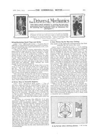
The sender of the following communication has been awarded the 10s. prize this week.
[1285] " A.C.T." (Sandbach) writes1—" I am sending. you particulars of a very useful jig which is designed for holding gear pinions when cutting keyways. It can be changed to cut one, two, three, four, or any desired number of slots in the pinion which may be required. For the purpose of convenience, I have drawn the elevation on the right-hand sidle of the plan in the sketch. In the sectional view the Tslotted base on the left-hand side is bolted on to the machine table of a slotting or a keyway-cutting machine. The base is bored out in the centre as shown, and a second jig is machined to drop into this boredout portion. The upper piece has three bosses cast on to it, through which set-screws are taken, which, serve to hold the pinion. Between the end of the setscrews, however, and the pinion are three hardened steel pieces, which are machined to the outside radius of the pinion which is being cut. Equi-distant and tapered slots are cut in any required number around the holder which has the east lugs on it, and a springcontrolled register pin runs through a boss cant on to the main base. The pinion is held as shown by the dotted line. The spring-controlled key drops into one of the slots and the keyway is cut, and then any other slots may be brought into register for the purpose of cutting a second, third, fourth or sixth keyway.
"When this jig is once made up, and suitable distance pieces have been made, it will be found a great convenience where a large number of pinions are continually being slotted, as the tool can be so quickly adjusted to differently-sized wheels. The various distance pieces and blocks need not be made up at first. They will accumulate as different work is done, until a complete set is obtained."