


A ROTARY-RECIPROCATING ENGINE.
Page 32
If you've noticed an error in this article please click here to report it so we can fix it.
A Résumé of Recently Published Patents.
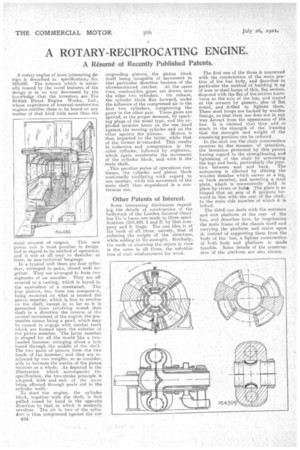
A rotary engine of most interesting design is described in specification, No. 164,602. The interest which is naturally roused by the novel features of the design is in no way decreased by the knowledge that the inventors are The British Diesel Engine Works, Ltd., whose experience of internal-combustion engines entitles them to be heard on any matter of that kind with more than the usual amount of respect. This new power unit is most peculiar in design and in regard to its method of operation, and is not at all easy to describe—at least, in non-technical language.
In a typical unit there. are four cyliii-: tiers, arranged in pairs, closed ends together. They are arranged to form two segments of an annulus. They are all secured to a casting, which is keyed to the equivalent of a crankshaft. The four pistons, too, form one component, being mounted on what is termed the piston member, which is free to revolve on the shaft, except in so far -as. it is prevented from revolving round that shaft in a directiOn the reverse of thss normal movement of the engine, the preventive means being a pawl, which may be caused to engage with ratchet, teeth which are formed upon the exterior of the piston member. The latter member is shaped for all. the world like a twoheaded hammer, swinging about a hide bored through the middle of the shaft. The two pairs of pistons form the two heads of the hammer, and they are reinforced by two weights, so as considerably to increase the inertia of the piston member as a whole. As depicted in the illustration which' accompanies the specification the two-stroke principle is adopted. inlet and exit of the gases being effected through ports cut in the cylinder walls.
To start the engine, the cylinder block, together .with the shaft, is first pulled round by hand in the opposite direction to that in which it normally revolves. The air in two of the cylin
ders is thus -compressed against the cor responding pistons, the piston block itself being incapable of movement in that particular direction because of the aforementioned ratchet. At the same time,. combustible gases axe drawn into the other two cylinders, On release, the cylinder block flies forward, under the influence of the compressed air in the first two cylinders, compressing the gasesin the other pair. These gases are ignited, at the proper moment, by sparking plugs of the usual type, and the exploded mixture bears on the one hand against the moving' cylinderand on the ,other against the pistons. Motion is thus imparted to the latter' while that of the former. is retarded. This .results in induction and compression in the other cylinder, followed by explosion, which again accelerates the Movement of the cylinder block, and with it the' :main shaft.
This peculiar series of operations continues, the -cylinder and piston block continually oscillating with regard to one another, while the movement of the :main shan thus engendered is a continuous one.
Other Patents of Interest.
Some interesting disclosures regarding the details of crinstruction of the bodywork of the London General Omnibus Co.'s buses are made in three specifications (164,480, 1 and 2) by that company arid S. Gage. The one idea is at the back of all three, namely, that of reducing the weight of "the structure, While adding to its strength. Similarly, the mode of attaining the object in view is the same in all three, the substitution of steel reinforcement for wood. The first one of the three is concerned with the construction of the main portion of the bus body, and describes in particular the method of building it up of iron or steel hoops of thin, flat section, disposed with the flat of the section transverse to the axis of the bus, and stayed at the corners by gussets, also of flat metal, and drilled to lighten them. These steel hoops are backed by wooden linings, so that their use does not in any way detract from the appearance of the bus. It is claimed that, they add so much to the strength of the framing that the strength and weight of the remaining portions can he reduced.
In the next one the chair construction receives its due measure of attention, the invention protected by this 'patent having regard to the strengthening and lightening of the chair by armouring the legs and hack, particularly the junc tion between seat and . back. The armouring is effected by slitting the wooden member which serves as a leg, or back member, and inserting a steel plate, which is conveniently held in place by-rivets or bolt.. The plate is so shaped that an arm of it projects forward in line with the seat of -the chair, to the main side member of which it is bolted_ The third one deals with the entrance and exit platform at the rear of , the' bus, and describes how, by lengthening the main frame of the chassis itself and carrying the platform and stairs upon it, instead of supporting them from the body of the bits, a lighter construction of both body and platform is made feasible. Some details of the construction of the platform are also shown.