


56. — Adjustment of A.E.C. Brakes. ,
Page 30
Page 31
If you've noticed an error in this article please click here to report it so we can fix it.
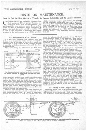
It is not only beneficial but essential that the brakes on a commercial motor vehicle be adjusted correctly, and in the case of the A.E.0 vehiclerthe adjustment is quite simple if the following method i5 carefully carried out in conjunction with the three diagrams given.
When commencing the adjustment the first thing to do is to jack up both rear wheels, then loosen the lock nut " H " on one of the stop screws "0," and' tighten the latter until the brake shoes rub on, the brake drums, then unscrew the stop screw two complete turns and tighten the locking.nut. Perform the same operation on the remainingathree stop screws, but be very careful, when adjusting these, to stop turning them as soon as the 1brake shoes show any signs of rubbing the brake drum. When all four atop screws have been subjected. to this treatment, attention should be directed to the near side adjustment rods " A " shown in diag,Tam 2. Loosen the lock nuts at each end of the rods, and
screw the adjustment rods until the levers " D " are in the position shown in the diagram. This applies to both rods Operating on the near side wheel. Special attention should be directed to the exact positions of " D " and " H," and in no circumstances should either of them be over the centre, or on. the right-hand side of the perpendicular line, when the brakes are off.
The lines " K" and " XI" in diagram 1 represent their correct positions when the brakes are on.
The off-side wheel should now receive attention. If the near side brakes have been adjusted according to the above instructions, the brake fulcrum levers ." D" and " H " are alreadytin their proper places, and do not require any alteration as regards angle. Before commencing the next operation make certain that the loCking nuts " 0 " and " P " at each end of the rod "A" are free.
Now operate rod " A " until " E," " F," and" G " are in a. perpendicular line. When this is so, tighten the locking nuts " 0 " and "P.!' Although the apparatus of the foot.brake is not shown it must be subjected-to the same treatment as the hand brake, as shown in diagram 1, and the corresponding bolts "E," "F," and "G" must be in a perpendicular line. The whole of the compensation of the brakes deEendszon this being the ease. Locking nuts
e a" B2 " should now be loosened and the turnbuckle " B " screwed up until the hand brake Will only traverse the quadrant to the sixth notch before it locks the wheels. After tightening the locking nuts the hand brake is now finished The turnbuckle "B" on the foot brake should be tightened until the pedal, when pressed down sufficiently to lock the wheels, is just one inch away from the floorboards.
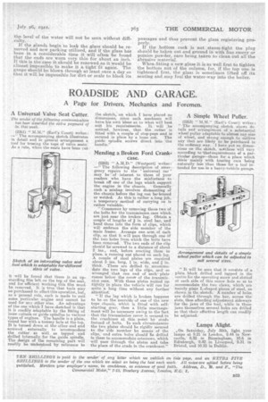
57.—Fitting Water Gauge Glasses.
The water gauge glass on a st6am wagon is a very important fitment and one which may cause Considerable trouble if it is neglected. Both the glass piece and its fittings should be kept very clean, otherwise
the level of the water will not be seen without difficulty.
If the glands begin to leak the glass should be removed and new packing utilized, and if the glass has been in a considerable time it will often. be found. that the ends are worn very thin for about an inch. If this is the case it, should be renewed as it would be almost impossible to make it a. tight-fit again. The gauge should be blown through at least once a day so that it will be impossible for dirt or cale to block its
passages and thus prevent the glass registering properly. If the bottom Cock is not steam-tight the plug should be taken out and ground in with fine emery or pumice powder, care being taken to clean out all the abrasive material.
When fitting a new glass it is as well first to tighten the bottom nut of the column, for, if the top one is tightened first, the glass is sometimes lifted off its Seating and may foul the water-way into the boiler.