 1
1 2
2 3
3 4
4 5
5 6
6 7
7 8
8 9
9 10
10 11
11 12
12 13
13 14
14 15
15 16
16 17
17 18
18 19
19 20
20 21
21 22
22 23
23 24
24 25
25 26
26 27
27 28
28 29
29 30
30 31
31 32
32 33
33 34
34 35
35 36
36 37
37 38
38 39
39 40
40 41
41 42
42 43
43 44
44 45
45 46
46 47
47 48
48 49
49 50
50 51
51 52
52 53
53 54
54 55
55 56
56 57
57 58
58 59
59 60
60 61
61 62
62 63
63 64
64 65
65 66
66 67
67 68
68 69
69 70
70 71
71 72
72 73
73 74
74 75
75 76
76 77
77 78
78 79
79 80
80 81
81 82
82 83
83 84
84 85
85 86
86 87
87 88
88 89
89 90
90 91
91 92
92 93
93 94
94 95
95 96
96 97
97 98
98 99
99 100
100 101
101 102
102 103
103 104
104 105
105 106
106 107
107 108
108 109
109 110
110 111
111 112
112 113
113 114
114 115
115 116
116 117
117 118
118 119
119 120
120 121
121 122
122 123
123 124
124 125
125 126
126 127
127 128
128 129
129 130
130 131
131 132
132 133
133 134
134 135
135 136
136 137
137 138
138 139
139 140
140 MEChAN ICS
Page 75
If you've noticed an error in this article please click here to report it so we can fix it.
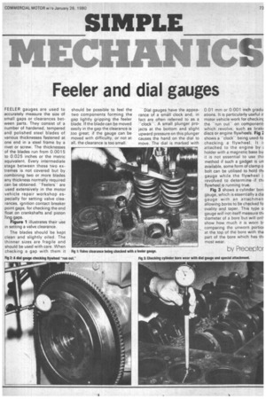
Feeler and dial gauges
FEELER gauges are used to accurately measure the size of small gaps or clearances between parts. They consist of a number of hardened, tempered and polished steel blades of various thicknesses fastened at one end in a steel frame by a rivet or screw. The thicknesses of the blades run from 0.0015 to 0.025 inches or the metric equivalent. Every intermediate stage between these two extremes is not covered but by combining two or more blades any thickness normally required can be obtained. "Feelers"' are used extensively in the motor vehicle repair workshop especially for setting valve clearances, ignition contact breaker point gaps, for checking the end float on crankshafts and piston 'ring gaps.
Figure 1 illustrates their use in setting a valve clearance.
The blades should be kept clean and slightly oiled. The thinner sizes are fragile and should be used with care. When checking a gap with them it should be possible to feel the two components forming the gap lightly gripping the feeler blade. If the blade can be moved easily in the gap the clearance is too great; if the gauge can be moved with difficulty, or not at all, the clearance is too small.
Dial gauges have the appearance of a small clock and, in fact are often referred to as a -clock-. A small plunger projects at the bottom and slight upward pressure on this plunger causes the hand on the dial to move. The dial is marked with 0.01 mm or 0.001 inch gradu ations. It is particularly useful ir motor vehicle work for checkint the -run outon component! which revolve, such as brakE discs or engine flywheels. Fig 2 shows a "clockbeing used fo checking a flywheel. It attached to the engine by E holder with a magnetic base bu it is not essential to use thi: method if such a gadget is un available, some form of clamp o bolt can be utilised to hold till gauge while the flywheel i: revolved to determine if thi flywheel is running true.
Fig 3 shows a cylinder bon gauge, which is essentially a dia gauge with an attachmen allowing bores to be checked fo ovality and taper. This type o gauge will not itself measure thi diameter of a bore but will on'. show how much it is worn b. comparing the unworn portior at the top of the bore with tha part of the bore which has thi most wear.
by Preceptor