


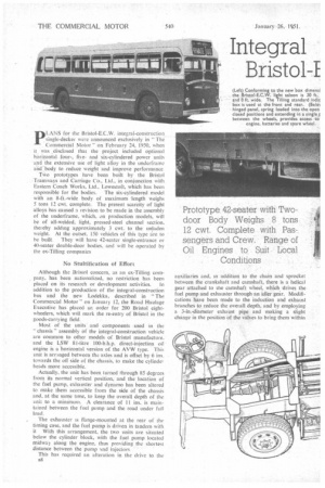
Integral Bristol-I
Page 42
Page 43
Page 44
Page 45
If you've noticed an error in this article please click here to report it so we can fix it.
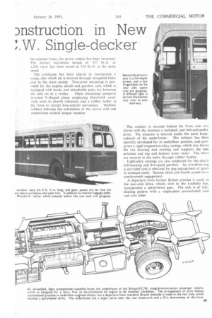
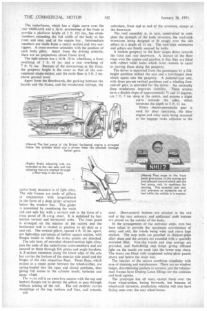
Dnstruction in New ;1W. Single-deci .. . and .body to reduce weight and improve performance Two prototypes have been built by the Bristol -Tramways and Carriage Co., Ltd., in conjunction with Eastern Coach Works, Ltd., Lowestoft, which has been responsible for the bodies. The six-cylindered model with an 8-ft.-wide body of maximum -length weighs 5 tons 12 cwt. complete. The present scarcity of light alloys has caused a revision to be made in the assembly of the underframe, which, on production models, will be of all-welded, light, pressed-steel channel section, thereby adding approximately 3 cwt. to the unladen weight. At the outset. 150 vehicles of this type are to be built. They will have 42-seater single-entrance or 40-seater double-door bodies, and will be operated by the ex-Tilling companies No Stultification of Effort Although the Bristol concern, as an ex-Tilling company, has been nationalized, no restriction has been placed on its research or development activities. In addition to the production of the integral-construction bus and the new Lodekka, described in "The Commercial Motor" on January 12, the Road Haulage Executive has placed ar. order for 200 Bristol eightwheelers, which will mark the re-entry of Bristol in the goods-carrying field. Most of the units and components used in the " chassis" assembly of the integral-construction vehicle are common to other models of Bristol manufacture. and the LSW 8i-litre l00-b.h.p. direct-injection oil engine is a horizontal version of the AVW type. This unit is arranged between the axles and is offset by 6 ins. towards the off side of the chassis, to make the cylindei heads more accessible. Actually, the unit has been turned through 85 degrees from its normal vertical position, and the location of the fuel pump, exhauster and dynamo has been altered to make them accessible from the side of the chassis and, at the same tune, to keep the overall depth of the unit to a minimum. A clearance of 11 ins, is maintained between the fuel pomp and the road under full load. The exhauster is flange-mounted at the rear of the timing case, and the fuel pump is driven in tandem with it With this arrangement, the two units are situated below the cylinder block, with the fuel pump located midway along the engine, thus providing the shortest distance between the pump •Ind injectors This has required an alteration in the drive to the auxiliaries and, in addition to the chain and sprocket between the crankshaft and camshaft, there is a helical gear attached to the camshaft wheel, which drives the fuel pump and exhauster through-an idler gear, Modifications have been made to the induction and exhaust branches to reduce the ovetall depth, and by employing a 3-in.-diameter exhaust pipe and making a slight change in the position of the valves to bring them within the cylinder bores, the power output has been increased. The former maximum torque of 337 lb-ft. at 1,200 r.p.irh has been raised to 345 lb.-ft at the same speed. The crankcase has been altered to incorporate a sump, into which oil is drained through elongated holes cast in the main casing. Two-point mounting is provided for the engine, clutch and gearbox unit, which is equipped with hooks and detachable jacks for lowering the unit on to a trolley. These mountings comprise inverted V-shaped plates employing Metalastik sandwich units to absorb vibration, and a rubber buffer at the front to restrictfore-and-aft movement. Snubber rubbers between the-extremities of the power unit and underframe control torque reaction The radiator is situated behind the front axle ani shares with the dynamo a jackshaft and belt-and-pulley drive. The dynamo is secured inside the main longi tudinals of the underframe. The radiator has been specially developed for its underfloor position, and comprises a rigid magnesium-alloy casting, which also forms the fan housing and cowling and supports the side oolumns and top and bottom water tanks The tubes are secured in the tanks through rubber bushes. • Light-alloy castings are also employed for the clutch bell-housing and five-speed gearbox An overdrive top is provided and is obtained by dog engagement of eeats In constant mesh. Second, third and fourth speeds liaN,e synchromesh engagement. A departure from former Bristol practice is made in the rear-axle drive, which, akin to the Lodekka bus, incorporates a spiral-bevel gear. The axle is of fully floating pattern with a -single-piece pressed-steel case and axle tubes The underframe, which has a slight curve over the rear whdel-arch anda 34-in. downsweep at the front to provide a platform height of 2 ft. 101 ins., has crossmembers extending the full width of the body at the front and rear, and at the engine bay.. Intermediate members are made from a centre section and two outriggers. A cross-member coincides with the position of each body pillar. Apart from the driving controls, there are no projections above frame level. The light saloon has a 16-ft. 10-in, wheelbase, a front overhang of 5 ft. 4i ins, and a rear overhang of 7 ft. 9i ins. Because of the downsweep at the front, the gangway height is the same as that of the conventional single-decker, and the main floor is 3 ft. 2 ins. above ground level. Apart from the floorboards, the packing between the boards and the frame, and the windscreen fairings, the entire body structure is of light alloy. The side frames are made of pillars, in conjunction with longitudinals in the form of a deep girder structure below the window line. This girder assembled by combining the waist rail and sole bar with a vertical web in the form of a truss panel of 16 s.w.g. sheet. It is stabilized by hatsection vertical and horizontal webs. The truss panel is arranged on the interior of the saloon and the horizontal web is riveted in position to do duty as a seat rail. The vertical pillars, spaced 4 ft. 21 ins, apart, are light-alloy extrusions of hollow square section, with flanges inside to which the stress panels are attached. The sole bars, of extruded channel-section light alloy, join the ends of the underframe'cross-members and are secured to them through fish plates and angle brackets. A Z-section extension along the lower edge of the sole bar carries the bottom of the exterior side panel and the hinges of the side inspection flaps. These flaps, which extend as a single panel between the wheel-arches, are spring-loaded into the open and closed positions, thus giving full access to the cylinder heads, batteries and spare wheel. The wAst rail is an open-box section with the top and bottom flanges cut to permit the pillars to pass through without joining of the rail. The rail exterior carries mouldings at the top, bottom and face, and extends, B10 unbroken, from end to end of the structure, except at the doorways. The roof assembly is, in turn, constructed to complete the strength of the body structure, the roof-stick extensions being designed to fit snugly over the side pillars to a depth of 11 ins. The roof-stick extensions and pillars-are finally seemed by bolts. A sunken gangway to the floor slopes down towards the front and rear doorways. A feature of the floor traps over the engine and gearbox is that they are fitted with rubber roller locks which form runners to assist in moving them along the gangway. The driver is separated from the passengers by a fUllheight partition behind the seat and a low-hinged door which opens into the gangway. A pedestal-type seat, with three pre-set vertical positions and a winding foreand-aft gear, is provided for the driver. An unusually deep windscreen improves visibility. These screens have a double slope of approximately 7 and 15 degrees, are 2 ft. 7 ins, deep at the centre, and assume a slight curve towards the sides, which increases the depth to 2 ft. 11 ins. Peters electro-pneumatic gear is used for door operation, the door engine and relay units being mounted in the luggage racks adjacent to the door. Door-control buttons are situated in the cab and at the rear entrance, and additional push buttons are placed on the outside of the body. In the arrangement of the entrance steps, care has been taken to provide the maximum convenience of entry and exit, the treads being wide and risers kept shallow. The step wells are panelled in chequer-plate alloy sheet and the corners are rounded with a specially extruded fillet. Non-slip treads and step nosings are provided, and flush-fitting step lamps giving diffused light on the treads are sunk into the lower step risers. The doors are fitted with toughened safety-glass panels above and below the waist line. The interior of the saloon combines simplicity with ease of cleaning and maintenance. There are no window ledges, dirt-retaining pockets or corners, and the tubularsteel frames have Dunlop Latex fillings for the cushions and back squabs. The prototype has all seats, except those over the front wheel-arches, facing forwards, but because of wheel-arch intrusion, production vehicles will also have facing seats over the rear wheel-boxes. Leather-cloth trimming is provided above waist-r dl level, including a cream material for the roof lining, and the corners at the floor level are rounded off with a light-alloy radiused fillet These vehicles may be required for town service— hence the two-door body—inter-urban work or for long distance runs. For this reason, the seats are comfortable and are generously spaced and, in addition to luggage racks, there is a 70-cubic-ft. locker which extends below the rear seat and floor. Complete with 42 passengers and crew. the prototype with 1w-door body weighs 8 tons 12 cwt.. the distribution being 3 tons 10 cwt. on the front axle and 5 tons 14 cwt on the rear. Tyre equipment is 9.00-in. by 20-in low pressure, with twins at the tear. The suspension system employs 3-in.-wide semielliptic springs, with rubber-bonded shackle pins fitted to the eyes, and telescopic shock absorbers at the front axle. The front springs are attached to the axle and have a steep taper towards the front.