


A Novel Self energizing Brake
Page 60
If you've noticed an error in this article please click here to report it so we can fix it.
THE name of Societe Anonyme des Amiens Etablissements Panhard and Levassor appears in patent No. 363,539, in which a novel form of selfenergizing brake is described. The chassis to which this brake is adapted should be fitted with a torque tube leading from the rear axle to a crossmember.
In the present case the spherical housing of the universal joint is slidably mounted and is held in place by springs (19). It is provided with a long boss and long splined portions so that rearward movement can take place. The front and rear brakes are both applied by a pedal (15), the effect of which is to cause the rear axle to move backward in relation to the chassis, owing to the retarding effect of its brakes. This rearward movement of the rear axle and its torque tube carries with it the boss of the pivot (13), but not the pivot of the lever (15), so that a pull is exerted on a rod (16), thereby imparting a rocking movement to a double lever (12) in the direction of the arrow, and in this manner adding to the power exerted on the brake pedal by the driver.
A Positively Engaging Free Wheel.
DESCRIBED in patent No. 363,551 by E. E. Morris and D. R. Morris, both of Manorfields, Leesons, Chialehurst, Kent, is a free wheel that does not depend upon the usual jamming action, but brings into engagement posi tive dogs for the forward drive, which release their engagement when the driven shaft overruns the driver.
The driving shaft '(A) is connected by means of the sleeve 0 to the sleeve C, which is internally threaded with a four. start screw, and is capable of sliding through its support bearing. The driven shaft terminates in a screw thread to match that of sleeve C, and is provided 1346 with a flange with buttress-shaped dogs, the slope of which on the one side is the same as the pitch of the screw thread. A similar flange, with opposing dogs, is formed on sleeve C, so that when the two meet a positive drive is produced. When the driven shaft is overrunning the driver the thread in sleeve C is allowed entirely to free itself from that on the driven shaft, but a collar (D) still remains in engagement. This collar is provided with four ratchet teeth, into which pawls (Di) can fall, so that when re-engagement of the threads takes place the four-start screw will find its way into engagement, a pin (M) causing the collar (D) at all times to rotate with the driven shaft.
When a bi-directional drive is required the dogs P can be brought into engagement with the dogs Q.
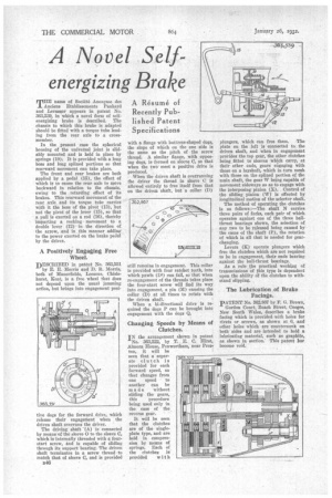
Changing Speeds by Means of Clutches.
IN the arrangement shown in patent No. 363,522, by T. E. C. Hirst, Almora House, Penwortham, near Preston, it will be seen that a separate clutch is provided for each forward speed, so that changes from one speed to another can he made without sliding the gears, this Procedure being used only in the case of the reverse gear.
It will be seen that the clutches are of the singleplate type, and are held in compression by means of springs. Each of the clutches is provided with plungers, which can free them. The plate on the left is connected to the driven abaft, and when in engagement provides the top gear, the other clutches being fitted to sleeves which carry, at their other ends, gears engaging with those on a layshaft, which in turn mesh with those on the splined portion of thc main shaft, the gear W being capable of movement sideways so as to engage with the interposing pinion (X). Control of the sliding pinion (W) is effected by longitudinal motion of the selector shaft. The method of operating the clutches is as follows :—The shaft N carries three pairs of forks, each pair of which operates against one of the three ballthrust bearings shown, the selection of any two to be released being caused by the cams of the shaft (P), the rotation of which is all that is needed for gearchanging. Levers (K) operate plungers which free the clutches which are not required to be in engagement, their ends bearing against the ball-thrust bearings. As a rule the practical working of transmissions of this type is dependent upon the ability Of the clutches to withstand slipping.
The Lubrication of Brake Facings.
pATENT No. 362,867 by F. G. Brown, Gordon Court, Beach Street, Coogee, New South Wales, describes a brake facing which is provided with holes for rivets or screws, as shown at 6, and other holes which are countersunk on both sides and are intended to hold a lubricating material, such as graphite, as shown in section: This patent her become void.