


Limiting the Rear-wheel Braking Effort
Page 62
If you've noticed an error in this article please click here to report it so we can fix it.
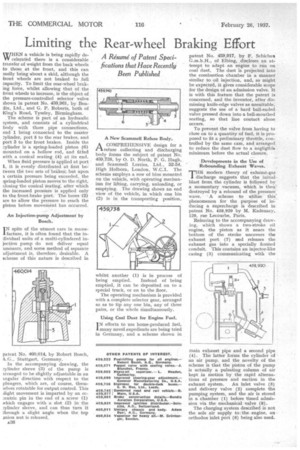
A Résumé of Patent Spedfications that Have Recently Been Published /HEN a vehicle is being rapidly deW celerated there is a considerable transfer of weight from the back wheels to those at the front, and this can easily bring about a skid, although the front wheels are not braked to full capacity. To limit the rear-wheel braking force, whilst allowing that of the front wheels to increase, is the object of the pressure-controlled selector valve shown in patent No. 459,961, by Bendix, Ltd., and G. P. Roberts, both of King's Road, Tyseley, Birmingham.
The scheme is part of an hydraulic system, and consists of a cylindrical body with thiee pipe connections, end 1 being connected to the master cylinder, port 5 to the rear brakes, and port 3 to the front brakes. Inside the cylinder is a spring-loaded piston (6) mounted on a hollow rod, and fitted with a conical seating (4) at its end.
When fluid pressure is applied at port it is evenly distributed at first between the two sets of brakeS; but upon a certain pressure being exceeded, the Tring-loaded piston moves to the right, closing the conical eating, after which the increased pressure is applied only to the front-brake port. The bores (2-) are to allow the pressure to reach the piston before movement has occurred.
An Injection-pump Adjustment by Bosch.
IN spite of the utmost care in manufacture, it is often found that the individual units of a multi-cylindered injection pump do not deliver equal amounts, and some method of separate adjustment is, therefore, desirable. A gcherne of this nature is described in
patent No. 460,014, by Robert Bosch, A.G., Stuttgart, Germany.
In the accompanying drawing, the 7.y-tinder sleeve (3) of the pump is arranged to be slightly adjustable in an angular direction with respect to the plungers, which are, of course, themwives rotatable for output control. This ,light movement is imparted by an cc:entric pin in the end of a screw (1) which engages with a slot (2) in' the :.ylinder sleeve, and can thus turn it through a slight angle when the top anion nut is released,
a36 A New &enamel!. Refuse Body.
ACOMPREHENSIVE design for a refuse collecting and discharging body forms the subject of patent No. 459,738, by 0. D. North, P. G. Hugh, and Scammell Lorries, Ltd., 52-54, High Holborn, London, W.C.1. The scheme employs a row of bins mounted on the vehicle, with operating mechanism for lifting, carrying, unloading, or emptying. The drawing shows an end view of the vehicle, in which one bin (2) is in the transporting position, whilst another (I) is in process of
being emptied. Instead of being emptied, it can be deposited on to a special truck, or on to the floor.
The operating mechanism is provided with a complete selector gear, arranged so as to tip any one bin, any of three pairs, or the whole simultaneously.
Using Coal Dust for Engine Fuel.
I N efforts to use home-produced fuel, many novel expedients are being tried in Germany, and a scheme shown in patent No. 459,917, by F. Schichau G,m.b.H., of Elbing, discloses an attempt to adapt an engine to run on coal dust. The dust is projected into the combustion chamber in a manner similar to oil injection, and, as might be expected, it gives considerable scope for the design of an admission valve. It is with this feature that the patent is concerned, and the inventor, after dismissing knife-edge valves as unsuitable; suggests the use of a hard ball-ended valve pressed down into a bell-mouthed sealing, so that line contact alone occurs.
To prevent the valve from having to close on to a quantity of fuel, it is proposed to fit a preliminary throttle, controlled by the same cam, and arranged to reduce the dust flow -to a negligible minimum before the actual closure.
Developments in the Use of Rebounding Exhaust Waves.
THR modern theory of exhaust-gas discharge suggests that the initial blast from the cylinder is followed by' a momentary vacuum, which is then' destroyed by a rebound of the pressure wave. A scheme to utilize this'. phenomenon for the purpose of inducing a supercharge is described in patent No. 458,920 by M. Kadenacy, 120, rue Lecourbe, Paris.
Referring to the accompanying drawing, which shows a two-stroke oil engine, the piston as it nears the bottom of the stroke uncovers the exhaust port (7) and releases the exhaust gas into a specially formed conduit. This contains an injector-like casing (5) communicating with the main exhaust pipe and a second pipe (4). The latter forms the cylinder of an air pump, and the novelty of the scheme is that the piston of the pump is actually a pulsating column of air kept in motion by the rapid alternations of pressure and suction in the exhaust system. An inlet valve (3) and delivery valve (2) complete the pumping system, and the air is stored in a chamber (1) before timed admission via the mechanical valve (8).
The charging system described is not the sole air supply to the engine, an orthodox inlet port (6) being also used.