


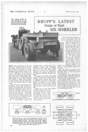
KRUPP'S LATEST
Page 56
If you've noticed an error in this article please click here to report it so we can fix it.
Design of Rigid
SIX-WHEELER
nurE motor department of the well1. known German armament firm of Fr. Krupp, of Essen, was one of the first concerns in Germany to devote attention to six-wheelers, having, early in 1925, designed one for loads up to
8 tons. The drive to the two rear axles of that vehicle was on somewhat novel lines; the propeller shaft transmitted its power to a single differential shaft which, in turn drove, through spur gearing, two shafts, with sprockets on each of their ends, the final drive to the road wheels being by roller chains.
Apart from the general demand for gear-driven rather than ehain-d riven vehicles, the arrangement did not prove altogether satisfactory, and in the following year Krupps brought out a new design of six-wheeler for 2-ton loads, in which both rear axles were directly driven by bevel gearing. Since then the company has further improved the design, and has now definitely adopted It in its latest 4-ton six-wheeler.
Although the chassis can be supplied with a six-cylindered engine, the standard vehicle is fitted with a fourcylindered power unit, developing 60 b.h.p. at from 1,400 r.p.m. to 1,590 r.p.m., the bore and stroke being 100 mm. and 160 mm. respectively. Ignitieu is by magneto, and both electric lighting and starting equipment are fitted.
The engine and clutch pit are built up in unit form with a main four-speed gearbox. At the rear of the latter is a supplementary gearbox with a pair of reduction spur gears, so that altogether, in addition to two reverse speeds, eight forward speeds, ranging from 21 m.p.h. to 22 m.p.h. at an engine speed of 1,400 r.p.m., are available.
Coming now to the bogie design; centrally located between the two axles, and arched to clear the propeller shaft, is a frame cross-member which forms the anchorage for two pairs of torque rods pivotally connected to lugs on each side of the worm geareases of the two rear axles. ' The rear-wheel suspension is also on novel lines, the usual pivoted semi-elliptic spring on each side of the chassis being conspicuous by its absence. Instead, there is on each side of the chassis, mounted centrally between the two axles, a pair of cast-steel triangular members pivoted at their lower inner ends to brackets on the crossmembers already alluded to. The upper extremities of the .triangular members are connected to a telescopic chamber, within which is fitted a strong helical spring.
The outer ends of the tri angular members are drilled to 'accommodate four large. diameter rubber-cushion, bearings for the axles.
The road wheels are of the G.F.Simplex cast-steel, detachable-rim type, shod with .18-in. by 7-in, low-pressure pneumatic tyres.
In addition to the usual hand-controlled emergency brake. servo-operated hydraulic brakes, actuated by pedal, are provided on all six -road wheels.
The chassis weighs 3 tons 2 ewt.. and is designed to carry a load, including the body, of 4 tons 2 cwt. The wheelbase is 15 ft., and the centre distance between the bogie axles is 3 ft, 11/ ins.. whilst the frnnt track is 5 ft. 11 in. and the rear track 5 ft. 6 ins.; the overall length is 20 ft.