


Nom Drivers &Mechanics
Page 24
Page 25
If you've noticed an error in this article please click here to report it so we can fix it.
TEN SHILLINGS WEEKLY is paid for the best communication received, and one penny a line of ten words For anything else published, with an allowance for photographs.
Send us au account of any special incident of your work or experience. If suitable, we will edit your notes, supply a sketch when required, and pay you for everything published. Mention your employer's name, in confidence, as evidence of good faith. Address to The Editor, TEE COMMERCIAL MOTOR, Rosebery Avenue, London, E.G.
Light Up Your Lamps At —
6.31, Thur.Nday ; 6.33, Friday ; 6.35, Saturday ; 6.38, Monday ; 6.40, Tuesday ; 6.42, Wednesday.
How to Reface the Clutch with Fibre.
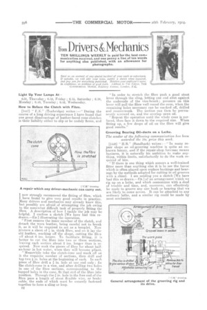
[1447] " F.N." (Tonbridge) writes :—" During the course of a long driving experience I have found that one great disadvantage of leather-faced cone-clutches is their liability either to slip or be unduly fierce, and A repair which any driver-mechanic can carry out.
I now strongly recommend the fitting of fibre, which I have found to give very good results in practice. Many drivers aud mechanics may already know this, but possibly are afraid of attempting the job owing to the somewhat difficult task of properly fitting the fibre. A description of how I tackle the job may be helpful. I enclose a sketch [We have had this redrawn.—En.] illustrating the operation,
" First remove the inner member of the clutch, and detach the worn leather, being careful not to break it, as it will be required to act as a templet. Now procure a sheet of 1.j, in, thick fibre, and on it lay the old leather, marking off the shape, cutting the fibre otr about 0 ins. longer. To facilitate fitting, it is better to cut the fibre into two or three sections, leaving each section about 2 ins, longer than is required. Now soak the pieces of fibre for abouthalfan-hour in hot water, when they will become pliant. " Meanwhile take the clutch-cone and mark: off on it the requisite number of sections, then drill and tap two in. holes at the beginning of each. In each piece of fibre drill a a in. hole at one end only ; fix the clutch-cone in a vice, and after drilling two holes in one of the fibre sections, corresponding to the tapped holes in the cone, fit that end of the fibre into position. Through the in. hole in the free end of the fibre pass a length of stout flexible wire, or brake cable, the ends of which must be securely fastened together to form a sling or loop.
"Iii order to stretch the fibre push a good stout lever through the sling, letting cue end abut against the underside of the vice-bench ; pressure on this lever will pull the fibre well round the cone, when the remaining holes necessary can be marked off, drilled and countersunk. The section can then be permanently screwed on, and the overlap sawn off. " Repeat the operation until the whole cone is surfaced, then face it down to the required size. When fitting up, a few drops of oil on the fibre will give good results."
Grooving Bearing Oil-ducts on a Lathe.
The sender of the following communication has been awarded the .10s. prize this week.
[1448] " H.R." (Sandbach) writes :—" In many repair shops an oil-grooving machine is quite an unknown luxury, and if the repair-shop foreman means business, it is naturally his ambition to make anything, within limits, satisfactorily to do the work required of him. " If there is one thing which annoys a well-trained fitter more than anything else it is to see the havoc which is often played upon replace bushings and bearings by the methods adopted for cutting in oil grooves with a chisel. I am sending you a sketch [We have had this re-drawn.—En.] of an arrangement which we rig up on a lathe, and which economizes with a deal of trouble and time, and, moreover, can effectively be made to groove any size bush or bearing that we are likely to come across. It can be attached to any ordinary lathe, and a similar rig could be made by most mechanics. " The drawing is practically self-explanatory, but the chief points to be considered are that. this arrangement should be bolted firmly to the lathe body and ;Ilso that the adjustable arm connecting the carriage with the horizontal disc should be parallel with the lathe-bed at each end of its stroke. The screw ia the tool-carriage-holder must be withdrawn before commencing operations, so as to enable the carriageto slide easily in either direction. The drive must be to proportioned as to enable the chuck to,make, one revolution whilst the tool is travelling the whole length of its stroke. An oil groove, after the outline of that shown in the small sketch, will thus be made which will feed oil equally all over the bearing.
'As an example, supposing I had to groove a bush in. in length: I should set the pin on the horizontal disc11,' in. out of centre adjust the connecting rod, lock the main carriage bed ; then. remove the. traverse screw from the tool carriage, set the grooving tool about in. inside the bush and start the lathe running.
" The carriage being free to slide, the connecting tad will cause the tool to travel just V, in., and the gearing being so arranged that the chuck will inak.-?. one revolution during the complete travel of the tool, an oil groove will be cut into the bearing of the reotdre-d length and pitch.'
Another Valve-lifting Tool.
[1A49] "W.E.D." (Ashb-ourne) writes :—" In the ' 1). and M.' pages of your issue of the 15th January last, I saw an interesting device, for facilitating the lifting of valves, which is made out of round bar. Now, 1 consider the valve-spring lifter I myself made is an improvement on this, as it saves tapping the cylinder casting in order to obtain a fulcrum ; I. claim it to he quite rigid in use. The enclosed sketch [We have had this re-drawn.—En] illustrates the tool and how to us? it.
" The lifter is constructed out of two pie-ce.s of mild steel strip, the overall length of each being about 18 ins., and the section of the metal 1, in. by in. I heated the ends of each piece and bent them as shown in the sketch, tapering off each to form a wedge.
"First taking the shorter piece, I bent it round untilits inside width was slightly larger than the diameter of the valve-tappet rods. I then shaped the remaining piece until it was a good working fit over the short one, and pivoted the two Frongs tegether by means of a cotter-pin, " After testing the device on the engine, I slightly altered, the bend of the prongs in order to 'enable the handles to be gripped by one hand, leaving the other hand free to extract or replace the cotter.
" Should spring-sleel be not available for the job, mild-steel or iron can be used, provided that the prongs are case-hardened by means of prussiate.. of potash or other mitable material. The hardening must, of course, he tione after the prongs are set." Improving the Coil Ignition.
[1450] " (Brooklyn, 13.3.A.) writes :—" Hay
ing.shad considerable trouble with battery and coil ignition on my stationary engine, which 1 use in the garage for running small machines, I decided to replace the battery by amore dependable source of ignition. My first thought was, of course, to install a high-tension magneto, but the coSt of such a device prompted me to think of some other scheme.
" Stored away with a number of other pieces of perimental apparatus I came across a friction electric machine, and itoccurred to me that the device would give a spark, having practically the same characteristics as that given by a high-tension magneto, and thus would be efficacious for ignition purposes, so I decided to utilize the machine.
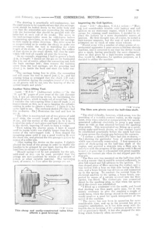
The fibre arm pivots round the half-time shaft.
The chief difficulty, however, which arose, was the providing of a suitable contact maker, as the equipment, even when rotated at comparatively low speeds, generated. sufficient electricity to jump a gap many times as wide as that situated between the sparking plug points. This necessitated my fitting up a quickacting make-and-break device, so that contact would be established practically before the spark had time to jump a-cross the closing gap between the contacts.
" I enclose a sketch [We have had this re-drawn.— Fa] showing the particular form of contact-maker which was eventually constructed. I first mounted a piece of clock-spring on the half-time shaft of the engine, and screwed a stop-pin into a fibre arm to interfere with the progress of the spring until it flexed to such a d.sgree that it rebounded with great rapidity against the contact pin when its end slipped past the stop-pin.
" The fibre arm was mounted on the bahr-time shaft in such a. manner that it could bt rotated sufficiently to give full-retard and full advance to the ignition. The cam-shaped piece of -fibre carrying the contact spring was turned with a boss on that side facing the fibre arm, and a brass ferrule was driven on and connected up to the spring. To conduct the current from time electrical machine to the spring, a brass brush, supported by means of a set-pin screwed into the fibre carrier, was fitted. The contact-pin was connected direct to the sparking plug, so that when the spring hit it thecircuit was established.
" I fitted up a condenser with the outfit-, and found that starting was thus -made quite easy, for it was merely necessary to give the .machine a couple of quick turns, when the energy stored in the condenser would produce a good fat spark irrespective of the spend of the machine.
" The device has now been in operation for some considerable time, and up to the present has given_ complete satisfaction, as it ha-s done away with the trouble due to burning of the platinum points on the coil -as previously fitted ; it has also stopped the misfiring which formerly often occurred.