


A Suspension System for . Battery-Electrics
Page 50
If you've noticed an error in this article please click here to report it so we can fix it.
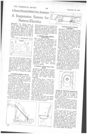
PATENT No. 591,416, from A. Morrison, 52, Woodhouse Road, Quorn, Leicestershire, covers a new scheme for the suspension of batterydriven vehicles. The aim is to provide a scheme more suited to the peculiar requirements of this type of vehicle, in which the major part of the weight is concentrated between the two sets of
Each wheel is independently sprung on a pail of quarter-elliptic springs (1 and 2); these are clamped to a body pillar at one end and pivoted to a plate (3), to which the road-wheel is attached. The lower spring takes most of the load, whilst the upper one acts as a torque rod taking most of the driving and braking forces. As this member is loaded mostly in either tension or compression, it may be replaced by a plain bar, A FOLDING „MOBILE CRANE
PATENT No. 591,821, from R. G. Le Tourneau Inc,, Peoria, Illinois, U.S.A., discloses a design for a powerful crane which can be folded compactly on to its vehicle for travelling.
The drawing shows the crane fully extended, and in broken lines, in a midway position. To perform the folding operation, the hook is first lowered and engaged with an eye (1). Locking pins (2) are then removed, after which a cable (3) is hauled in swinging the mast forwards and downwards until it comes to rest on a spring-loaded abutment (4). 'le normal lifting cable (5) is paid out during this operation and serves to control the descent. When the mast is
down, locking pins (6) are removed and the boom (7) can then descend, controlled by the paying out of the mast cable while the hook cable is wound in. When in the fully stowed position, the whole of the crane lies well within the wheelbase of the vehicle.
A TORSION-FREE SPRING MOUNTING
TO eliminate the transmission of twisting stresses to the springs is the aiin of a type of mounting shown in patent No. 590,887. The patentees are H. Carver and Jonas Woodhead and Sons, Ltd., Kirkstall Road, Leeds.
The spring employed has its top leaf forged into a solid eye (1), which is bored to receive a pin (2) formed on a trunnion block, the latter being pivotally shackled to the chassis on bore 3. A co-axial trunnion (4) fits a bore formed in the upturned end of the third leaf. The second leaf lies flat against the .undersick.. of the trunnion block, the body (5) of which is cylindrical. The whole spring is thus free to rock on a longitudinal axis when torsional stresses are applied.
A STRONG, CHEAP SEAT FOR BUSES
A BUS or coach seat forms the subject of patent No. 591,439, by John C.
Beadle, Ltd., Spital Street, Dartford, and others. The object of the dcsign is to provide a robust construction that can be easily and cheaply made and assembled.
The drawing shows a section of a double seat mounted on a bent-steel frame for bolting to the floor. Crossrails are also formed on the frame— four on the seat portion and two on the back. The back and the seat are made from two pieces of stout canvas (1 and 2). These are attached to the cross-rails (3 and 4) and run one over the back and one over the bottom, their two free ends meeting under the seat, where strainer bolts (5) unite them.
By adjusting these bolts, any desired tension can be applied to the canvas strips. The latter can be further upholstered in any desired manner. FACILITATING ENGINE ASSEMBLY
PATENT No, 591,521 refers to crankcases in which the crankshaft, complete with its main bearings, is slid into position through one end of the crankcase. With such a scheme, it has previously been found desirable to make the bearing housings of successively differing diameters, because all those except the last one have to pass through other bores. A scheme which permits all the bearinghousings to be of the same diameter, with a consequent saving in machining, is shown in this patent by E. Bugatti, Paris.
The drawing shows a section of a crankcase across the point at which a main bearing is located The crankshaft runs in a split bearing (1) which is a close fit in the bore in the surrounding web. The bore is, however, to size only on its upper hall, the lower being cleared away, as shown at 2, so that the bearing can be freely passed through it.
To lock the bearing in position, a slidable block is placed between the guides (3) and pulled into place by bolts in the holes (4). • The clearance space is occupied by a semi-circular strip of steel having a wavy outline.
GUIDE TO MIXTURE STRENGTH A NOVEL means for measuring the
mixture strength of an engine is described in patent No. 591,808 by Bendix Aviation Corporation, South Bend, Indiana, U.S.A.
A short, tubular member is placed in the induction pipe of the engine, and in this member is a small loop of fine wire, from which two leads are extended. The loop is warmed by passing a current through, but is cooled, and its resistance reduced, by the cold mixture flowing past.
In the petrol pipe there is a second device, which alters its resistance in accordance with the quantity of fuel flowing at any moment, These two varying resistances arc equated by a Wheatstone7brid3e circuit, which converts the out-of-balance current into a simple dial reading. The dial is calibrated in terms of richness and leanness, with the correct value in the middle, so that little skill is required to take a reading. The fuel-pipe resistance is covered by a further patent, No. 591,818.