


Patents Completed.
Page 22
If you've noticed an error in this article please click here to report it so we can fix it.
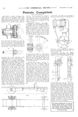
STEERING AXLE. — Bideau. — No. 2,801, dated 4th February, 1907.—The main axle (1) is provided with forked pieces (2, 3) adapted to receive a spindle (4) keyed thereto by pins (5, 6). The axle journal (7) is provided with projections (8, 9, 10) which are bored to receive the outer race rings of ball bearings (12, 13) upon the spindle (4). The projections (8, 10), with their ball bearings (12, 13), are for the purpose of resisting the strains of the bending couple, whilst the central
projection (9) is only subjected to the vertical pressure due to the axle load.
MOUNTING OF ROAD WHEELS.— Molesworth and Another.—No. 26,844, dated 26th November, 1906.—The inner wheel (A) of each pair of wheels, is arranged to be the driving wheel, and, as usual, it has a chain or sprocket wheel (B) secured to its inner side. The cylindrical portion of this wheel, serves as a brake drum in the usual manner, The outer wheels (C) are free to rotate on bushes (D), around the eccentrics of which the wheels are mounted_ An arm (E), extending upwards, is connected by chains to two points of the frame of the vehicle to limit the amount of movement of the bush around the axle. In order that the pressure upon the driving wheel, or upon the freewheel, may be increased, or decreased, as desired, the plate (E) is provided with an arm (G) extending downwards. The arms (F, G) are coupled by cords to the opposite arms of a lever (H) which is connected by a link (I) to a hand
lever (J). Thus, whenever it is desired to cause one or other set of two wheels to have the greater portion of weight placed upon them, the lever is pressed either' forward or backward, according to the wheels selected.
RESILIENT WHEEL. —Rowcliffe. — No. 20,437, dated 14th September, 1908.A tubular sleeve (d) through which the wheel axle (b) passes, is provided with a flange (e) extending at right angles to the axis of the wheel. The hub (f) of the wheel is made of larger diameter than usual, so as to admit of the resilient medium (c) being-placed between it, and the tubular sleeve. One side of the hub is faced, so that the flange (e) on the tubu lar boss may fit against it. The hub (f) is slightly conical, as is also the tubular sleeve (d). The resilient medium (c) is placed in the annular space between the hub (g), and the sleeve (d), and is securely held in position by the disc ring (g) and the bolts (i).
LUBRICATOR.—Nacke (Boult).—No. 26,728, dated 24th November, 1906.—A collecting tank (A) is arranged beneath the engine casing (B) and is connected with a supply tank (C) by means of a pipe (D) through which the oil from the collecting tank may be forced by means of a pump (E). The tank (C) is provided with outlets (F) controlled by valves (G), these outlets being at the bottom of the supply tank so that the oil may be completely emptied therefrom. The tank (C) is provided with a gauge glass (H) so that the level of the oil may be indicated outside the tank. The oil pumped up from the collecting tank (A) through the pipe (B) does not pass directly into the supply tank (C), but first passes through
F:91 a filter (K). An inlet (L) is provided at the top of the filter for the admission of fresh oil ; a drain cock (NI) is fitted to the bottom through which the dirty oil may be drawn off.
SPANNER.— Brearley. — No. 29,694, dated 31st December, 1906.—The spanner consists of two sliding members (A, B)
provided wi h jaws (Al, 131), The members (A, B) are held together by the two straps (C, D) so as to prevent lateral displacement, but, at the same time, to allow longitudinal movement relatively to one another. The member (A) has a series of half circular grooves on its inner surface, and the member (B) has a similar ,,et of grooves, but with intervening spaces between them of lesser dimensions than those between the grooves on the member (A), When the members (A, B) are placed in the positions shown in Figs. I and 2, the grooves (P, R) coincide, thus forming a complete circular hole into which a key (K) is inserted and thereby securely locks the two together.